Introduction
Imagine knowing who’s at your door without having to leave your couch—or even your workplace. Smart doorbells are transforming home security and convenience by giving you instant access to your front door, no matter where you are. This article will guide you through creating a smart doorbell using Arduino ESP32 Cam, a Wi-Fi-enabled microcontroller known for its cost-effectiveness and versatility. Whether you’re a beginner or an experienced tech enthusiast, this project will provide you with a practical, DIY solution to upgrade your home’s security.
What is a Smart Doorbell?
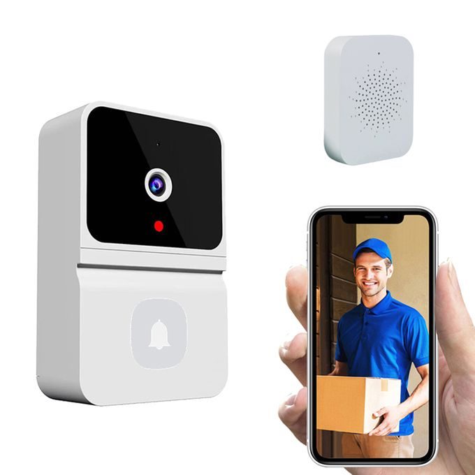
A smart doorbell is an advanced version of a traditional doorbell that incorporates technology for added security and convenience. Typically equipped with a camera, microphone, and speaker, it lets homeowners see, hear, and even communicate with visitors remotely. Many smart doorbells also offer features like motion detection and video recording, making them a popular choice for home automation.
Why Choose Arduino ESP32 Cam for a Smart Doorbell?
The ESP32 Cam module by Arduino is a powerful, budget-friendly option for building a smart doorbell. Equipped with Wi-Fi, a built-in camera, and the ability to stream live video, ESP32 Cam is perfect for capturing and transmitting images of visitors directly to your smartphone or computer.
Key Features of a Smart Doorbell with Arduino ESP32 Cam
Real-Time Video Streaming
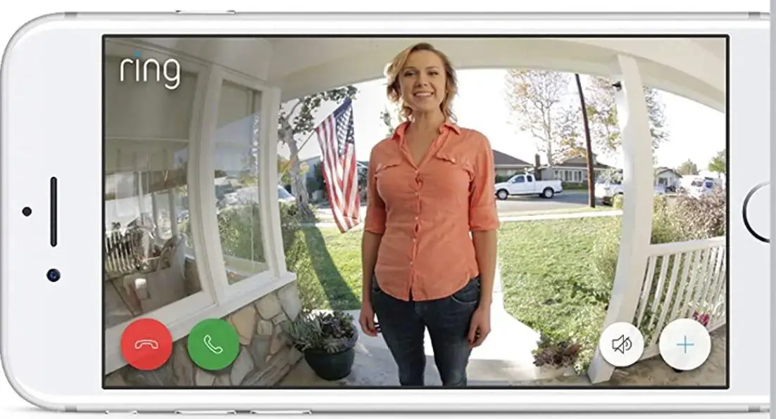
The ESP32 Cam allows you to stream live video, enabling you to view visitors on your smartphone as they approach the door.
Motion Detection
With an added PIR (Passive Infrared) sensor, your doorbell can detect movement and automatically send alerts to your device.
Read Also IoT Health Monitoring with LoRa, ESP32 Arduino for Real-Time Tracking
Two-Way Audio Communication
By adding a microphone and speaker, you can talk to visitors in real-time, even if you’re away from home.
Image Capture and Storage
With SD card support, the ESP32 Cam can store images, allowing you to review past footage if necessary.
Remote Access
Using Wi-Fi, you can monitor your smart doorbell from anywhere, giving you peace of mind when you’re not at home.
Getting Started: Materials You’ll Need
To build your own smart doorbell with Arduino ESP32 Cam, here’s what you’ll need:
- Arduino ESP32 Cam module: This will serve as the main component for video streaming and processing.
- FTDI programmer: For programming the ESP32 Cam.
- MicroSD card: Optional, for storing captured images.
- PIR motion sensor: For detecting movement at your doorstep.
- Jumper wires: To connect different components.
- Push button: To act as the doorbell button.
- 5V power source: To power your ESP32 Cam module.
- Microphone and speaker (optional): For two-way audio communication.
Setting Up the Arduino IDE for ESP32 Cam
- Install the ESP32 Board Support Package: Open Arduino IDE, go to File > Preferences, and paste this URL into the Additional Boards Manager URLs:
https://dl.espressif.com/dl/package_esp32_index.json. - Select the ESP32 Cam Board: In Tools > Board, select “AI-Thinker ESP32-CAM.”
- Configure Upload Speed and Port: Set the upload speed to 115200 and select the appropriate port for your FTDI programmer.
- Install Required Libraries: Install libraries such as WiFi, ESP32CAM, and CameraWebServer.
Step-by-Step Guide to Building the Smart Doorbell
The Schematic Diagram
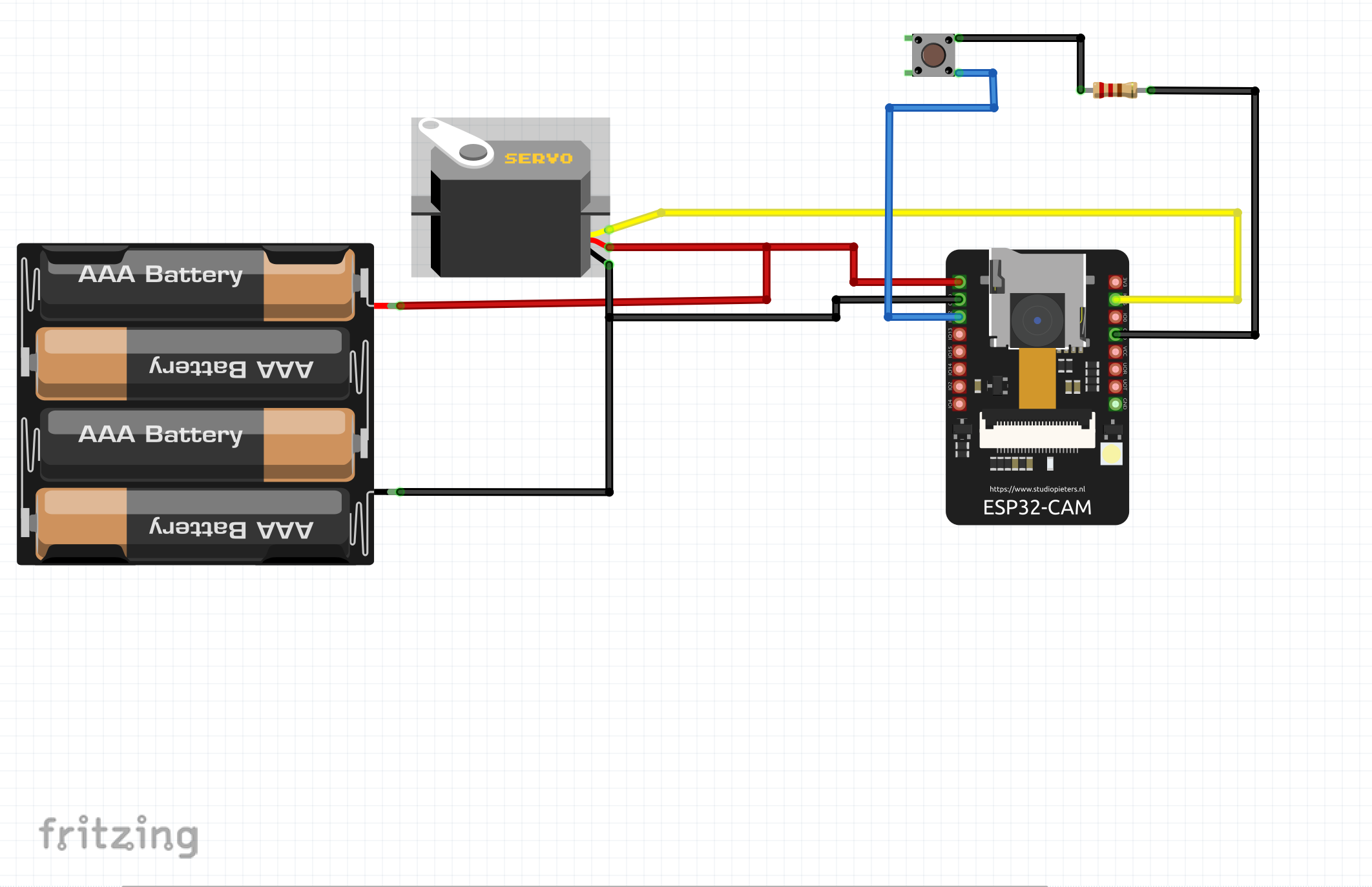
The connection is done as shown above. We added a servo motor so that the own can tilt or rotate the ESP32 Cam to any direction within 180 degree that he or she wants.
Explanation of Schematic Diagram
The FTDI programmer to your ESP32 Cam to upload the code. Ensure the following connections:
- ESP32 Cam RX to FTDI TX, TX to FTDI RX
- GND to GND and 5V to VCC
Programming the ESP32 Cam for Smart Doorbell
#include "esp_camera.h"
#include "SPI.h"
#include "driver/rtc_io.h"
#include "ESP32_MailClient.h"
#include <FS.h>
#include <SPIFFS.h>
#include <WiFi.h>
//additional libs for video stream
#include "esp_timer.h"
#include "img_converters.h"
#include "Arduino.h"
#include "fb_gfx.h"
#include "soc/soc.h" //disable brownout problems
#include "soc/rtc_cntl_reg.h"  //disable brownout problems
#include "esp_http_server.h"

// REPLACE WITH YOUR NETWORK CREDENTIALS
const char* ssid = "Galaxy A51 917E";
const char* password = "tosin@345";
//for vid stream
#define PART_BOUNDARY "123456789000000000000987654321"

// To send Emails using Gmail on port 465 (SSL), you need to create an app password: https://support.google.com/accounts/answer/185833
#define emailSenderAccount    "[email protected]"
#define emailSenderPassword   "vvmg yhvp mxpp jrgi"
#define smtpServer            "smtp.gmail.com"
#define smtpServerPort        465
#define emailSubject          "ESP32-CAM Photo Captured"
#define emailRecipient        "[email protected]"

#define CAMERA_MODEL_AI_THINKER

#if defined(CAMERA_MODEL_AI_THINKER)
  #define PWDN_GPIO_NUM     32
  #define RESET_GPIO_NUM    -1
  #define XCLK_GPIO_NUM      0
  #define SIOD_GPIO_NUM     26
  #define SIOC_GPIO_NUM     27

  #define Y9_GPIO_NUM       35
  #define Y8_GPIO_NUM       34
  #define Y7_GPIO_NUM       39
  #define Y6_GPIO_NUM       36
  #define Y5_GPIO_NUM       21
  #define Y4_GPIO_NUM       19
  #define Y3_GPIO_NUM       18
  #define Y2_GPIO_NUM        5
  #define VSYNC_GPIO_NUM    25
  #define HREF_GPIO_NUM     23
  #define PCLK_GPIO_NUM     22
#else
  #error "Camera model not selected"
#endif

// The Email Sending data object contains config and data to send
SMTPData smtpData;

// Photo File Name to save in SPIFFS
#define FILE_PHOTO "/photo.jpg"

//video stream
static const char* _STREAM_CONTENT_TYPE = "multipart/x-mixed-replace;boundary=" PART_BOUNDARY;
static const char* _STREAM_BOUNDARY = "\r\n--" PART_BOUNDARY "\r\n";
static const char* _STREAM_PART = "Content-Type: image/jpeg\r\nContent-Length: %u\r\n\r\n";

httpd_handle_t stream_httpd = NULL;

static esp_err_t stream_handler(httpd_req_t *req){
  camera_fb_t * fb = NULL;
  esp_err_t res = ESP_OK;
  size_t _jpg_buf_len = 0;
  uint8_t * _jpg_buf = NULL;
  char * part_buf[64];

  res = httpd_resp_set_type(req, _STREAM_CONTENT_TYPE);
  if(res != ESP_OK){
    return res;
  }

  while(true){
    fb = esp_camera_fb_get();
    if (!fb) {
      Serial.println("Camera capture failed");
      res = ESP_FAIL;
    } else {
      if(fb->width > 400){
        if(fb->format != PIXFORMAT_JPEG){
          bool jpeg_converted = frame2jpg(fb, 80, &_jpg_buf, &_jpg_buf_len);
          esp_camera_fb_return(fb);
          fb = NULL;
          if(!jpeg_converted){
            Serial.println("JPEG compression failed");
            res = ESP_FAIL;
          }
        } else {
          _jpg_buf_len = fb->len;
          _jpg_buf = fb->buf;
        }
      }
    }
    if(res == ESP_OK){
      size_t hlen = snprintf((char *)part_buf, 64, _STREAM_PART, _jpg_buf_len);
      res = httpd_resp_send_chunk(req, (const char *)part_buf, hlen);
    }
    if(res == ESP_OK){
      res = httpd_resp_send_chunk(req, (const char *)_jpg_buf, _jpg_buf_len);
    }
    if(res == ESP_OK){
      res = httpd_resp_send_chunk(req, _STREAM_BOUNDARY, strlen(_STREAM_BOUNDARY));
    }
    if(fb){
      esp_camera_fb_return(fb);
      fb = NULL;
      _jpg_buf = NULL;
    } else if(_jpg_buf){
      free(_jpg_buf);
      _jpg_buf = NULL;
    }
    if(res != ESP_OK){
      break;
    }
    //Serial.printf("MJPG: %uB\n",(uint32_t)(_jpg_buf_len));
  }
  return res;
}

void startCameraServer(){
  httpd_config_t config = HTTPD_DEFAULT_CONFIG();
  config.server_port = 80;

  httpd_uri_t index_uri = {
    .uri       = "/",
    .method    = HTTP_GET,
    .handler   = stream_handler,
    .user_ctx  = NULL
  };

  //Serial.printf("Starting web server on port: '%d'\n", config.server_port);
  if (httpd_start(&stream_httpd, &config) == ESP_OK) {
    httpd_register_uri_handler(stream_httpd, &index_uri);
  }
}

void setup() {
  WRITE_PERI_REG(RTC_CNTL_BROWN_OUT_REG, 0); //disable brownout detector

  Serial.begin(115200);
  Serial.println();

  pinMode(2, INPUT_PULLUP);

  // Connect to Wi-Fi
  WiFi.begin(ssid, password);
  Serial.print("Connecting to WiFi...");
  while (WiFi.status() != WL_CONNECTED) {
    delay(500);
    Serial.print(".");
  }
  Serial.println();

  if (!SPIFFS.begin(true)) {
    Serial.println("An Error has occurred while mounting SPIFFS");
    ESP.restart();
  }
  else {
    delay(500);
    Serial.println("SPIFFS mounted successfully");
  }

  // Print ESP32 Local IP Address
  Serial.print("IP Address: http://");
  Serial.println(WiFi.localIP());

  camera_config_t config;
  config.ledc_channel = LEDC_CHANNEL_0;
  config.ledc_timer = LEDC_TIMER_0;
  config.pin_d0 = Y2_GPIO_NUM;
  config.pin_d1 = Y3_GPIO_NUM;
  config.pin_d2 = Y4_GPIO_NUM;
  config.pin_d3 = Y5_GPIO_NUM;
  config.pin_d4 = Y6_GPIO_NUM;
  config.pin_d5 = Y7_GPIO_NUM;
  config.pin_d6 = Y8_GPIO_NUM;
  config.pin_d7 = Y9_GPIO_NUM;
  config.pin_xclk = XCLK_GPIO_NUM;
  config.pin_pclk = PCLK_GPIO_NUM;
  config.pin_vsync = VSYNC_GPIO_NUM;
  config.pin_href = HREF_GPIO_NUM;
  config.pin_sscb_sda = SIOD_GPIO_NUM;
  config.pin_sscb_scl = SIOC_GPIO_NUM;
  config.pin_pwdn = PWDN_GPIO_NUM;
  config.pin_reset = RESET_GPIO_NUM;
  config.xclk_freq_hz = 20000000;
  config.pixel_format = PIXFORMAT_JPEG;

  if(psramFound()){
    config.frame_size = FRAMESIZE_UXGA;
    config.jpeg_quality = 10;
    config.fb_count = 2;
  } else {
    config.frame_size = FRAMESIZE_SVGA;
    config.jpeg_quality = 12;
    config.fb_count = 1;
  }

  // Initialize camera
  esp_err_t err = esp_camera_init(&config);
  if (err != ESP_OK) {
    Serial.printf("Camera init failed with error 0x%x", err);
    return;
  }

}


void loop() {

if(digitalRead(2)== LOW){
  capturePhotoSaveSpiffs();
sendPhoto();

delay(3000);
SPIFFS.remove("/photo.jpg");
 ESP.restart();
}
 // Start streaming web server
  // startCameraServer();
  delay(1);
}


// Check if photo capture was successful
bool checkPhoto( fs::FS &fs ) {
  File f_pic = fs.open( FILE_PHOTO );
  unsigned int pic_sz = f_pic.size();
  return ( pic_sz > 100 );
}

// Capture Photo and Save it to SPIFFS
void capturePhotoSaveSpiffs( void ) {
  camera_fb_t * fb = NULL; // pointer
  bool ok = 0; // Boolean indicating if the picture has been taken correctly

  do {
    // Take a photo with the camera
    Serial.println("Taking a photo...");

    fb = esp_camera_fb_get();
    if (!fb) {
      Serial.println("Camera capture failed");
      return;
    }

    // Photo file name
    Serial.printf("Picture file name: %s\n", FILE_PHOTO);
    File file = SPIFFS.open(FILE_PHOTO, FILE_WRITE);

    // Insert the data in the photo file
    if (!file) {
      Serial.println("Failed to open file in writing mode");
    }
    else {
      file.write(fb->buf, fb->len); // payload (image), payload length
      Serial.print("The picture has been saved in ");
      Serial.print(FILE_PHOTO);
      Serial.print(" - Size: ");
      Serial.print(file.size());
      Serial.println(" bytes");
    }
    // Close the file
    file.close();
    esp_camera_fb_return(fb);

    // check if file has been correctly saved in SPIFFS
    ok = checkPhoto(SPIFFS);
  } while ( !ok );
}

void sendPhoto( void ) {
  // Preparing email
  Serial.println("Sending email...");
  // Set the SMTP Server Email host, port, account and password
  smtpData.setLogin(smtpServer, smtpServerPort, emailSenderAccount, emailSenderPassword);

  // Set the sender name and Email
  smtpData.setSender("ESP32-CAM", emailSenderAccount);

  // Set Email priority or importance High, Normal, Low or 1 to 5 (1 is highest)
  smtpData.setPriority("High");

  // Set the subject
  smtpData.setSubject(emailSubject);

  // Set the email message in HTML format
  smtpData.setMessage("<h2>Photo captured with ESP32-CAM and attached in this email.</h2>", true);
  // Set the email message in text format
  //smtpData.setMessage("Photo captured with ESP32-CAM and attached in this email.", false);

  // Add recipients, can add more than one recipient
  smtpData.addRecipient(emailRecipient);
  //smtpData.addRecipient(emailRecipient2);

  // Add attach files from SPIFFS
  smtpData.addAttachFile(FILE_PHOTO, "image/jpg");
  // Set the storage type to attach files in your email (SPIFFS)
  smtpData.setFileStorageType(MailClientStorageType::SPIFFS);

  smtpData.setSendCallback(sendCallback);

  // Start sending Email, can be set callback function to track the status
  if (!MailClient.sendMail(smtpData))
    Serial.println("Error sending Email, " + MailClient.smtpErrorReason());

  // Clear all data from Email object to free memory
  smtpData.empty();
}

// Callback function to get the Email sending status
void sendCallback(SendStatus msg) {
  //Print the current status
  Serial.println(msg.info());
}

//THE CODE IS NOT COMPLETE, leave a comment for the full code
Explanation of the Arduino Code
Write or upload code to set up your ESP32 Cam as a live video server. Here’s a basic outline:
- Initialize the Camera: Start by configuring the camera and setting resolution.
- Set up Wi-Fi Connection: Connect the ESP32 Cam to your home network.
- Start the Web Server: Allow video streaming on a local IP address.
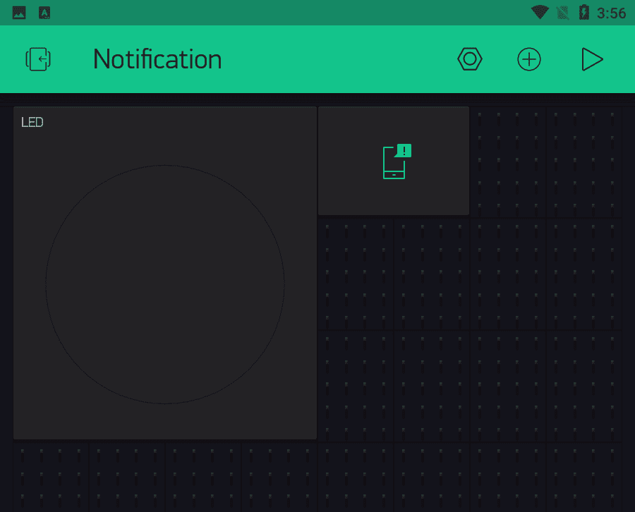
Adding Motion Detection
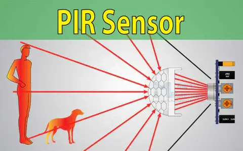
We attached the PIR sensor to our ESP32 Cam. And we programmed the ESP32 to send a notification to our phone when movement is detected.
Add Push Button Functionality
Attach a push button to the ESP32 Cam. When pressed, it should trigger a specific action, such as capturing an image or sending a notification.
Integrate Two-Way Audio (Optional)
Adding a microphone and speaker lets you communicate with visitors. This may require additional modules and complex coding but enhances functionality.
Read Also 10 Arduino-Based Automation Projects You Can Build at Home
Programming The Arduino ESP32 Cam Code
Here’s the code structure. You can modify it to suit your specific setup:
#include "esp_camera.h"
#include <WiFi.h>

// Camera setup
void setup() {
  Serial.begin(115200);
  WiFi.begin("your_SSID", "your_PASSWORD");
  while (WiFi.status() != WL_CONNECTED) {
    delay(1000);
    Serial.println("Connecting...");
  }
  startCameraServer();
}

void loop() {
  // Handle PIR sensor and button events
}
How to Access Your Doorbell’s Live Feed
- Connect to the Local IP: After uploading the code, open a browser, and enter the ESP32 Cam’s IP address to view the live video.
- Access Remotely: Use port forwarding on your router to access the camera feed from anywhere. This may require additional security settings.
Enhancing Security with Notifications
Consider setting up IFTTT (If This Then That) integrations or using Telegram for instant notifications on your smartphone when the PIR sensor detects movement. This feature can improve the doorbell’s security aspect by allowing you to respond quickly to any activity near your door.
Powering Your Smart Doorbell
Using a 5V Adapter
The ESP32 Cam requires a steady 5V power source. Use a reliable adapter to avoid power fluctuations that may disrupt its performance.
Battery Backup Option
Consider adding a battery backup, especially if you live in an area prone to power outages. Rechargeable batteries can be integrated for continuous operation.
Customizing Your Doorbell with the RemoteXY App
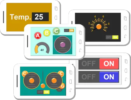
The RemoteXY app allows you to build custom interfaces for controlling Arduino projects. Use it to create a basic control panel for your smart doorbell, giving you access to features like turning the camera on/off, capturing photos, or activating notifications.
Advantages of Using Arduino ESP32 Cam for Your Smart Doorbell
- Affordable Solution: Compared to commercially available smart doorbells, this DIY project is cost-effective.
- Customizable: With Arduino, you can customize every aspect of your smart doorbell to suit your needs.
- No Subscription Fees: Unlike branded products, there are no ongoing fees for cloud storage or app usage.
- Data Privacy: All data is stored locally, giving you complete control over your information.
Troubleshooting Common Issues
Issue 1: “Failed to Connect to Wi-Fi”
Double-check your SSID and password, and ensure the ESP32 Cam is within range of your Wi-Fi router.
Issue 2: Camera Module Not Recognized
Make sure all connections are secure and that you’re using the correct board and settings in the Arduino IDE.
Issue 3: Power Issues
If the ESP32 Cam keeps restarting, it may not be receiving enough power. Use a more stable 5V power source.
Maintenance Tips for Your Smart Doorbell
- Regularly Clear SD Card Storage: If you’re using an SD card, regularly clear unnecessary files to prevent storage issues.
- Check Wi-Fi Connectivity: Ensure that your Wi-Fi signal remains strong for consistent performance.
- Weatherproofing: Protect your doorbell from harsh weather conditions if installed outdoors.
Future Upgrades and Add-Ons
- Cloud Storage for Images and Video: Consider using cloud services to store captured images securely.
- Night Vision: Upgrade with infrared LEDs for visibility in low light.
- Face Recognition: Integrate OpenCV for facial recognition, providing personalized alerts.
Conclusion
Building a smart doorbell with Arduino ESP32 Cam is a rewarding project that enhances home security and automation. With features like live streaming, motion detection, and remote access, this DIY smart doorbell is both functional and cost-effective. Plus, with endless possibilities for upgrades, you can customize it to meet your specific needs.
Read Also How to Build an IoT Based Temperature Control Poultry Farm Arduino
By following this guide, you can make your home a little smarter and a lot safer. Ready to start building? Share your experience and questions in the comments below!
FAQs on Smart Doorbell with Arduino ESP32 Cam
Can I use the ESP32 Cam without an FTDI programmer?
Yes, you can use other methods like direct programming, but an FTDI programmer simplifies the process.
Is it possible to access the video feed remotely?
Yes, by setting up port forwarding on your router, you can access the feed remotely.
What is the range of the PIR sensor?
Typically, a PIR sensor can detect motion within 5-7 meters, but this may vary depending on the model.
Can I add night vision to the ESP32 Cam?
Yes, you can add night vision capabilities to your ESP32 Cam by installing infrared (IR) LEDs. This will allow the camera to capture images in low-light conditions. Ensure the IR LEDs are compatible with your setup and positioned to illuminate the camera’s field of view.
How do I secure the remote access to my smart doorbell feed?
Securing remote access is essential. Start by enabling a strong password for your Wi-Fi network and consider using a Virtual Private Network (VPN) for an added layer of security. Avoid sharing the remote access link publicly, and regularly check your router settings to prevent unauthorized access.
cool