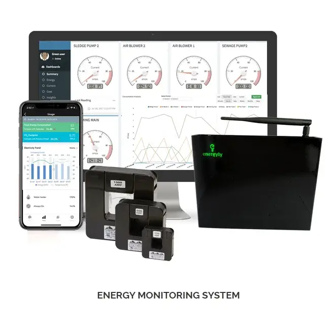
What is a home energy monitoring system? Ever opened your electricity bill and wondered, “Where is all this power going?” You’re not alone. As energy prices rise and environmental concerns grow, understanding and managing home energy consumption has become more important than ever.
Enter the Home Energy Monitoring System. With the help of an Arduino board, you can create a system to monitor energy usage, identify wastage, and save money—all while contributing to a greener planet. Let’s break down how this works, step by step.
What Is a Home Energy Monitoring System?
A Quick Overview
A home energy monitoring system tracks the electrical energy consumed by devices in your home. It displays data such as voltage, current, power, and total energy consumption.
Why Monitor Energy?
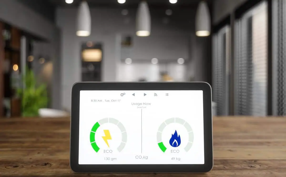
Monitoring energy isn’t just about cutting costs; it’s about making informed decisions. Knowing which devices consume the most power helps you adopt more energy-efficient practices.
Read Also: How to Convert Telegram Mini Apps Airdrop to Local Currency: A Step-by-Step Guide
Why Use Arduino for Home Energy Monitoring?
Arduino is an affordable, user-friendly microcontroller platform that’s perfect for DIY electronics projects. It simplifies hardware-software integration, making it an ideal choice for building an energy monitoring system.
Read Also: Smart Doorbell for Home Automation Arduino ESP32 Cam
Benefits of Using Arduino
- Cost-Effective: Arduino boards are inexpensive compared to commercial energy monitors.
- Customizable: You can tailor the system to meet your specific needs.
- Educational: Building the system teaches valuable coding and electronics skills.
How Does an Arduino-Based Energy Monitoring System Work?
Core Components
An Arduino-based energy monitor uses sensors to measure electrical parameters. These sensors send data to the Arduino, which processes and displays the information.
The Monitoring Process
- Step 1: Current and voltage sensors collect data.
- Step 2: The Arduino calculates power and energy based on sensor readings.
- Step 3: Data is displayed on an LCD and equally sent to an IoT platform like Zafron for analysis.
Read Also Arduino RGB LED Controller: Adjust Colors With Potentiometers.
Components Needed for the Project
Hardware Requirements
- Arduino Board: Arduino Nano is ideal.
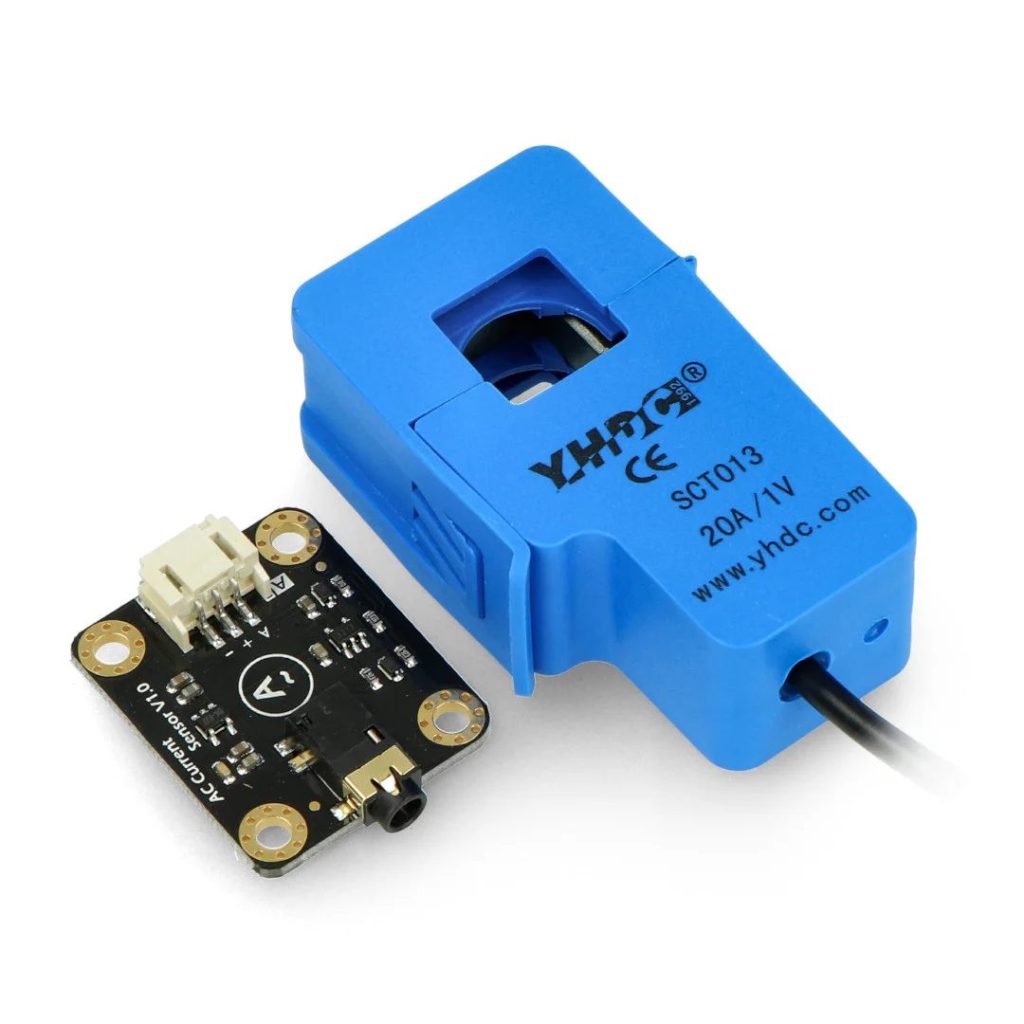
- Current Sensor: SCT-013 or ACS712.
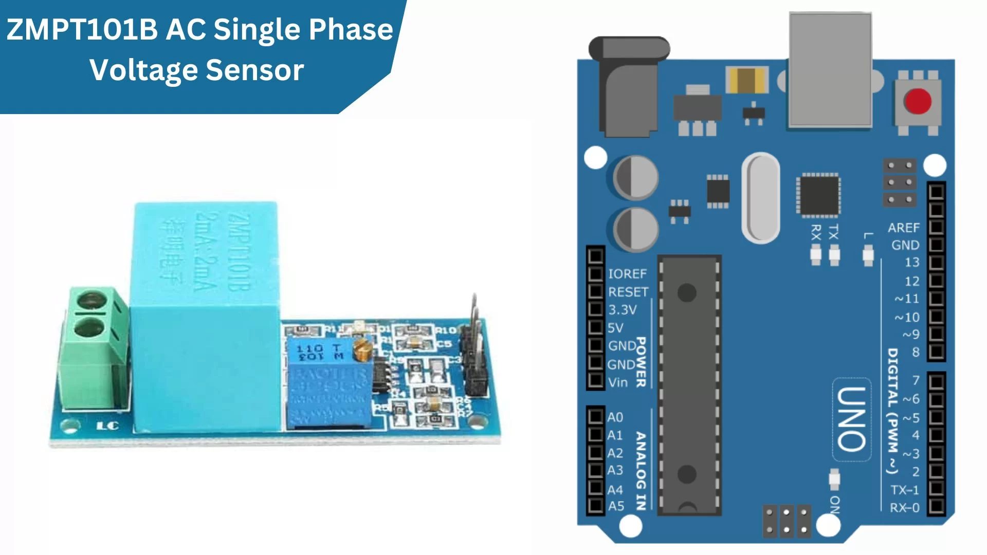
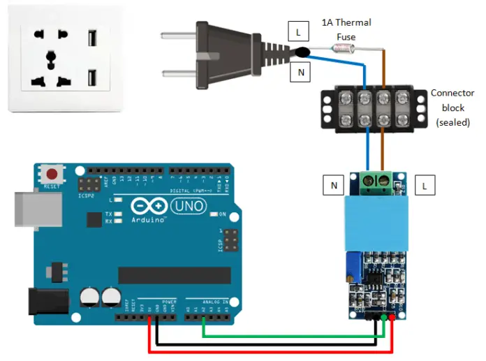
- Voltage Sensor: ZMPT101B or similar.
- LCD Module: A 20×4 LCD for displaying data.
- Resistors and Capacitors: For voltage division and filtering.
- Wi-Fi Module: Optional, for IoT integration (ESP8266).
- Power Supply and Cables: To power the system.
Software Requirements
- Arduino IDE: For writing and uploading code.
- Libraries: Such as EmonLib for energy calculations and LiquidCrystal for LCD control.
Read Also: Traffic Light System: How To Simulate a Traffic Signal Using LEDs.
Step-by-Step Guide to Building the System
The Circuit Design
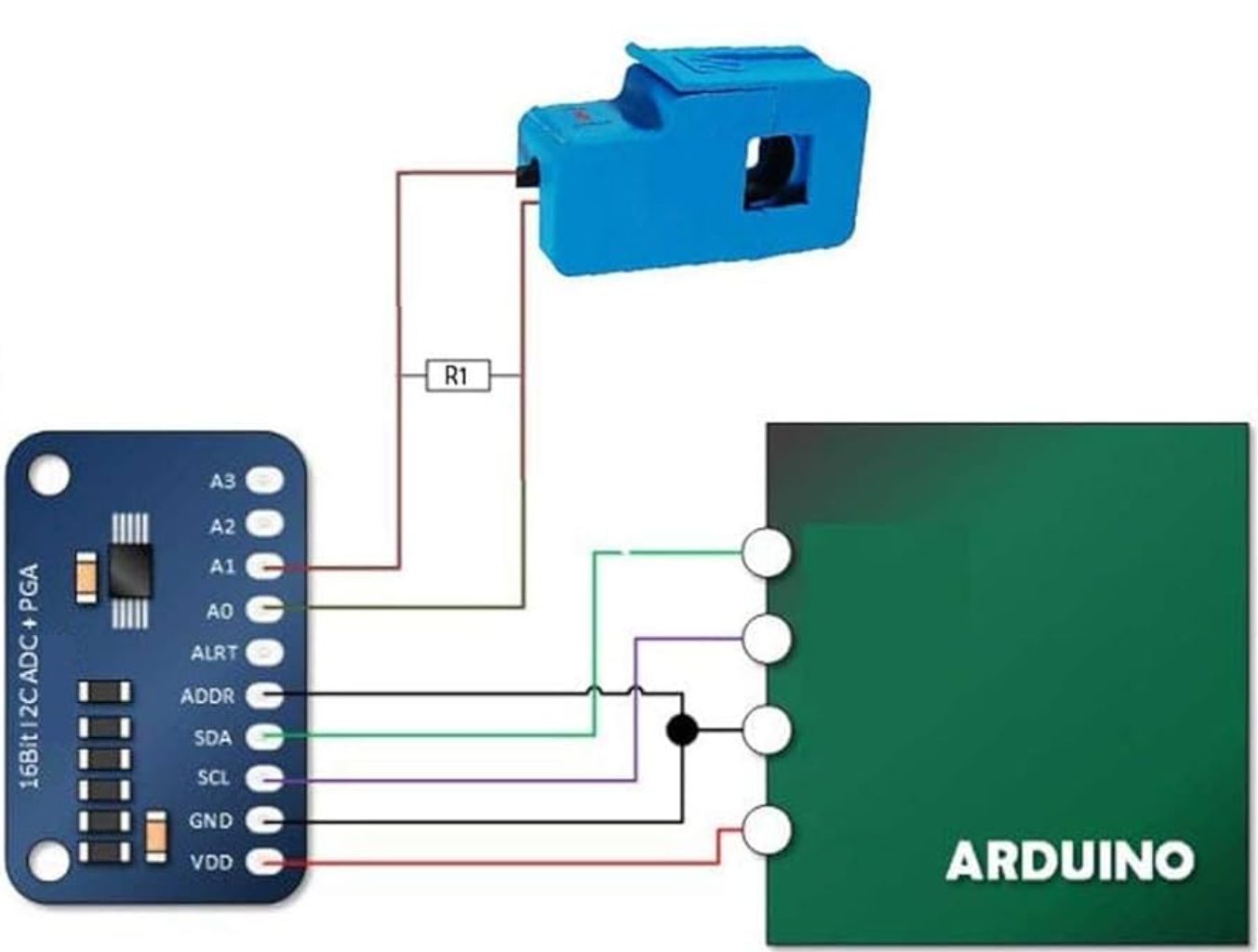
We used the current sensor and connected it as shown in the ‘circuit diagram shown above. Since the current sensor module uses the I2C communication protocol, the Arduino board pin was the Analog pin 4 and 5 respectively for the SCL and the SDA.
The circuit diagram above allowed us to measure the Alternating Current (A.C) voltage using the analogRead protocol of the Arduino pin. This allowed us to measure the effectively the A.C voltage of the supply.
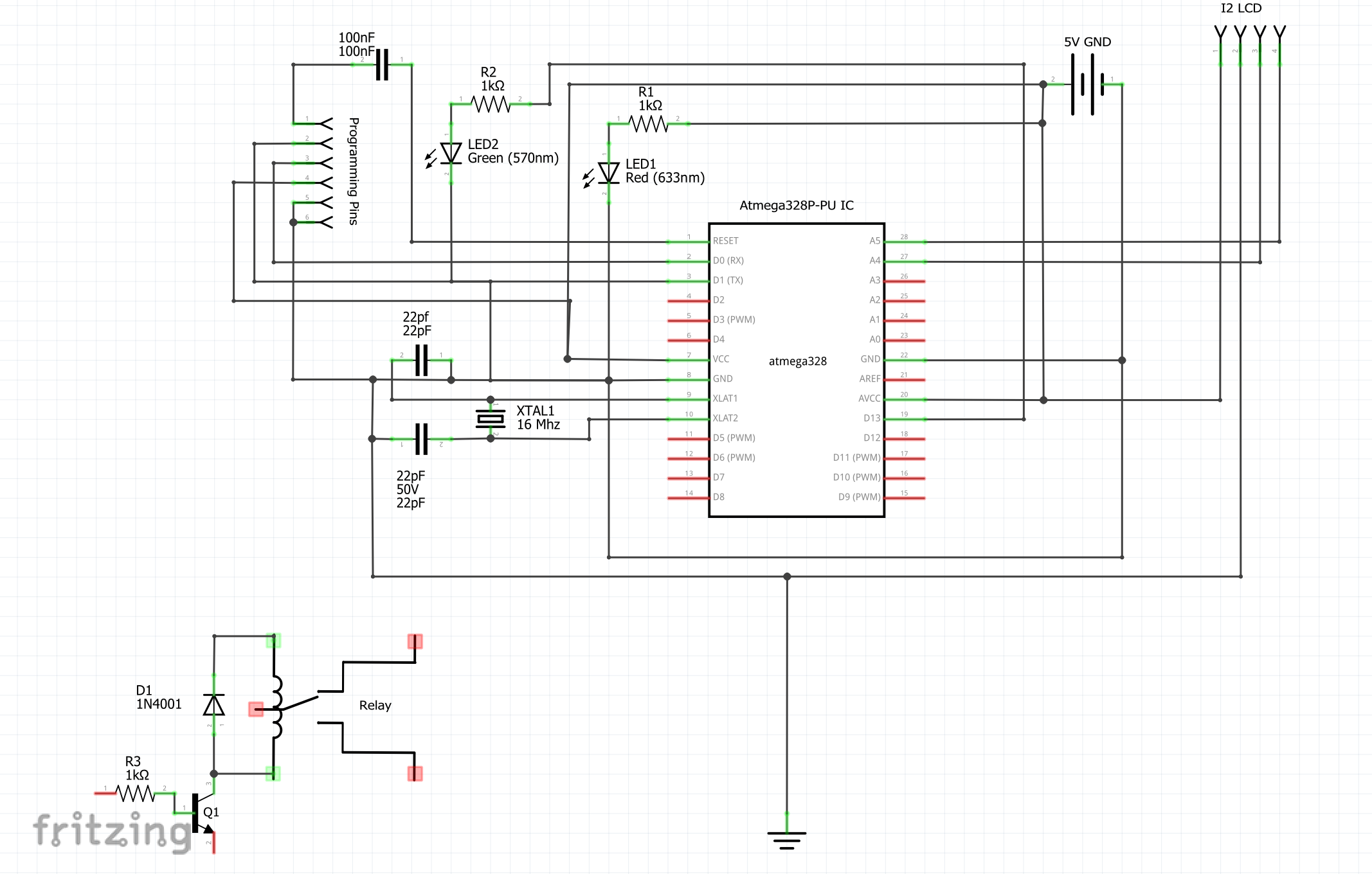
Explanation of the Circuit Diagram
We used the standalone design for the Arduino board to design and construct the whole project of energy monitoring. The ATmeaga328P IC was used as the brain of the design. The 22pF capacitors was used as filters.
- Connect the Current Sensor: We ensured we connected this to the live wire of the circuit load we want to monitor.
- Set Up the Voltage Sensor: Connect it to the AC mains while ensuring proper insulation for safety.
- Wire the Arduino to Sensors: Use analog pins for sensor inputs and digital pins for LCD control.
Writing The Arduino Code
//include the libraries used for the program
#include <PZEM004Tv30.h>        //include the PZEM lib
#include <Wire.h>               //include the I2C lib
#include <LiquidCrystal_I2C.h>  //include the I2C LCD lib
#include <SoftwareSerial.h>
#include "RTClib.h"

int ledPin = 13; // Pin connected to the LED
int blinkCount = 0; // Variable to track the number of blinks

bool GenMode, NepaMode, onUtility, onGen;

//define the serial comm. pins for the PZEM and MCU
PZEM004Tv30 pzem(4, 5);  // Software Serial pin 4 (RX) & 5 (TX)
SoftwareSerial arduino(2, 3);

// set the LCD address to 0x3F for a 16 chars and 2 line display
LiquidCrystal_I2C lcd(0x27, 16, 4);
//define variables
float currentRead, voltageRead, pfRead,frequencyRead, powerRead, energyRead;
// Floats for resistor values in divider (in ohms)
float R3 = 10000.0;
float R4 = 15000.0;
float adc_Genvoltage = 0.0;
float in_Genvoltage, in_GenCurrent, in_GenFrequency, in_GenPower, in_GenEnergy, in_GenPf;
// Float for Reference Voltage
float ref_voltage = 5.0;
int adc_Genvalue = 0;
int readGenSensor;

RTC_Millis rtc;

void setup() {
  Serial.begin(115200);
  arduino.begin(115200);
  pinMode(onlineGenButton, INPUT);
  lcd.init();       //begin the I2C lcd
  lcd.clear();      //clear the LCD
  lcd.backlight();  // Make sure backlight is on
  //state the inputs and putputs
  pinMode(houseLiveWire, OUTPUT);
  pinMode(houseNeutralWire, OUTPUT);
  pinMode(kickStartRelay, OUTPUT);
  pinMode(GenStateRelay, OUTPUT);
  pinMode(GenSupplyPin, INPUT);

  // Print a message on both lines of the LCD.
  lcd.setCursor(2, 0);  //Set cursor to character 2 on line 0
  lcd.print("Hello world!");

  lcd.setCursor(0, 1);  //Move cursor to character 2 on line 1
  lcd.print("Welcome Emmanuel");
  delay(3000);
  lcd.clear();  //clear the LCD

  #ifndef ESP8266
    while (!Serial); // wait for serial port to connect. Needed for native USB
#endif

    // following line sets the RTC to the date & time this sketch was compiled
  rtc.begin(DateTime(F(__DATE__), F(__TIME__)));
    // This line sets the RTC with an explicit date & time, for example to set
    // January 21, 2014 at 3am you would call:
    // rtc.adjust(DateTime(2014, 1, 21, 3, 0, 0));
}
////WHEN TURNING ON THE GENERATOR IGNITION, THE "ON" STATE IS WHEN  PINS 1 & 6 IS DISCONNECTED////
///PINs 2 & 5 is ALSO DISCONNECTED.////
////THE OFF STATE IS WHEN THESE ABOVE PINS ARE CONNECTED////
////HOWEVER, TO START, PINS 3 & 4 MUST BE CONNECTED WHILE THE FIRST 4 PINS ABOVE WILL DISCONNECT////
////TO TURN OFF GENERATOR, PINS 1 & 6 CONNECTED, PINS 2 & 5 CONNECTED and  PINS 3 & 4 DISCONNECTED////
int checkGenOnlineButton(){
  int readOnlineButton = digitalRead(onlineGenButton);
  if (readOnlineButton == HIGH) {
  blinkCount = 0;
  startGen();
  }

  else{
      blinkCount = 4;
        }
    Serial.print("readOnlineButton: ");
  Serial.println(readOnlineButton);
}

void startGen(){
  // if (trialTimes == true) {
    // blinkCount = 0;
if (blinkCount < 4) { // Check if the number of blinks is less than 5
    digitalWrite(ledPin, HIGH); // Turn the LED on
    turnOnGen();
    delay(300); // Wait for 100 milliseconds
    startIgna();
    delay(3000);
    GenVoltageLevel(); //check the supply voltage of Gen
    if (in_Genvoltage >= 80.00) {
    Serial.println("Gen started successfully");
    blinkCount = 5;
    }
    digitalWrite(ledPin, LOW); // Turn the LED off
    Serial.println("Couldn't start Gen");
    delay(2000); // Wait for 2000 milliseconds
    turnOnGen();
    blinkCount++; // Increment the blink count
  }
    else {
    // If the number of blinks is 5, do nothing
    Serial.println("Max. number of trials reached");
      }
      Serial.print("Trial Times = ");
      Serial.println(blinkCount);
  }


void startIgna() {
  digitalWrite(kickStartRelay, HIGH);
  digitalWrite(GenStateRelay, LOW);
}
void turnOnGen() {
  digitalWrite(kickStartRelay, LOW);
  digitalWrite(GenStateRelay, LOW);
}
void turnOffGen() {
  digitalWrite(kickStartRelay, LOW);
  digitalWrite(GenStateRelay, HIGH);
}

float GenVoltageLevel(){
   readGenSensor = analogRead(GenSupplyPin);
  // Determine voltage at ADC input
   adc_Genvoltage  = (readGenSensor * ref_voltage) / 1024.0;
   // Calculate voltage at divider input
   in_Genvoltage = adc_Genvoltage / (R4/(R3+R4)) ;
   in_Genvoltage = map(in_Genvoltage, 0.01, 7.90, 12.00, 240.00);
   in_Genvoltage = constrain(in_Genvoltage, 12.00, 240.00);
   if(in_Genvoltage >= 70){
      in_GenCurrent = 0.429;
      in_GenFrequency = 46.0;
      in_GenPf = 1.3;
      in_GenPower = in_GenCurrent * in_Genvoltage;
      in_GenEnergy = in_GenPower * 0.1;
   }
   if(in_Genvoltage <= 30){
      in_GenCurrent = 0.0;
      in_GenFrequency= 0.0;
      in_GenPf = 0.0;
      in_GenPower = in_GenCurrent * in_Genvoltage;
      in_GenEnergy = in_GenPower * 0.1;
   }
  // Serial.print("Gen Voltage Level: ");
  // Serial.println(in_Genvoltage);
  return in_Genvoltage, in_GenCurrent, in_GenEnergy, in_GenFrequency, in_GenPf, in_GenPower;
}

float pzemEnergyReadings() {
  float voltage = pzem.voltage();
  if (voltage != NAN) {
    // Serial.print("Voltage: ");
    // Serial.print(voltage);
    // Serial.println("V");
  } else {
    Serial.println("Error reading voltage");
  }

  float current = pzem.current();
  if (current != NAN) {
    // Serial.print("Current: ");
    // Serial.print(current, 2);
    // Serial.println("A");
  } else {
    Serial.println("Error reading current");
  }

  float power = pzem.power();
  if (current != NAN) {
    // Serial.print("Power: ");
    // Serial.print(power);
    // Serial.println("W");
  } else {
    Serial.println("Error reading power");
  }

  float energy = pzem.energy();
  if (current != NAN) {
    // Serial.print("Energy: ");
    // Serial.print(energy, 2);
    // Serial.println("kWh");

  } else {
    Serial.println("Error reading energy");
  }

  float frequency = pzem.frequency();
  if (current != NAN) {
    // Serial.print("Frequency: ");
    // Serial.print(frequency, 0);
    // Serial.println("Hz");
  } else {
    Serial.println("Error reading frequency");
  }

  float pf = pzem.pf();
  if (current != NAN) {
    // Serial.print("PF: ");
    // Serial.println(pf);
  } else {
    Serial.println("Error reading power factor");
  }
  voltageRead = voltage;
  currentRead = current;
  powerRead = power;
  energyRead = energy;
  frequencyRead = frequency;
  pfRead = pf;
  return currentRead, voltageRead, powerRead, energyRead, frequencyRead, pfRead;
}


bool checkGenParameters(){
  GenVoltageLevel();
  if(in_Genvoltage <= 50){
    GenMode = false;
  }
   if(in_Genvoltage >= 60){
    GenMode = true;
  }
  return GenMode;
}

bool checkNepaParameters(){
pzemEnergyReadings();
//check if there Utility voltage and if it is within safe range and turn on to switch to NEPA
  if ((voltageRead >= 160) && (voltageRead <= 241)) {
    digitalWrite(houseLiveWire, HIGH);
    digitalWrite(houseNeutralWire, HIGH);
    Serial.println("NEPA TURNED ON");
    turnOffGen();
    NepaMode = true;
  }
  //if however it is low voltage or high voltage turn off utility
  if (((voltageRead >= 30) && (voltageRead <= 89)) || (voltageRead >= 281)) {
    digitalWrite(houseLiveWire, LOW);
    digitalWrite(houseNeutralWire, LOW);
    //Serial.println("NEPA TURNED OFF");
    NepaMode = false;
    startGen();
    //Serial.println("GEN TURNED ON DUE TO LOW OR HIGH VOLTAGE");
  }
  //if there is no utility voltage, switch back to Generator
  if ((isnan(voltageRead)) || ((voltageRead >= 1) && (voltageRead <= 29))) {
    lcd.clear();
    digitalWrite(houseLiveWire, LOW);
    digitalWrite(houseNeutralWire, LOW);
    //Serial.println("NEPA TURNED OFF");
    NepaMode = false;
    startGen();
    //Serial.println("GEN TURNED ON DUE TO NO UTILITY SUPPLY");
  }
  return NepaMode;
}

void lcdDisplayGenValues(){
  GenVoltageLevel();
    //send to the ESP01 dev board via serial comm.
  arduino.print(in_Genvoltage);     arduino.print("A");
  arduino.print(in_GenCurrent);     arduino.print("B");
  arduino.print(in_GenPower);       arduino.print("C");
  arduino.print(in_GenEnergy);      arduino.print("D");
  arduino.print(in_GenFrequency);   arduino.print("E");
  arduino.print(in_GenPf);          arduino.print("F");
  arduino.print("\n");
//print the energy parameters on the LCD
  lcd.setCursor(1, 0);  //print current
  lcd.print("Cur ");
  lcd.setCursor(0, 1);
  lcd.print(in_GenCurrent);
  lcd.print("A");
  //print voltage
  lcd.setCursor(6, 0);
  lcd.print("Volt ");
  lcd.setCursor(6, 1);
  lcd.print(in_Genvoltage, 0);
  lcd.print("V");
  //print the frequency
  lcd.setCursor(12, 0);
  lcd.print("FRQ ");
  lcd.setCursor(12, 1);
  lcd.print(in_GenFrequency, 0);
  lcd.print("Hz");
  //print the power
  lcd.setCursor(-3, 2);  //Move cursor to character 1 on line 3
  lcd.print("PWR ");
  lcd.setCursor(-4, 3);
  lcd.print(in_GenPower, 0);
  lcd.print("W");
  //print energy
  lcd.setCursor(2, 2);
  lcd.print("ENGY ");
  lcd.setCursor(1, 3);
  lcd.print(in_GenEnergy, 2);
  lcd.print("kWH");
  //print the power factor
  lcd.setCursor(9, 2);
  lcd.print("P.F ");
  lcd.setCursor(9, 3);
  lcd.print(in_GenPf, 1);
    //print out the values read on the S. monitor
  Serial.print("Voltage: ");
  Serial.print(voltageRead);
  Serial.print("V");
  Serial.print(" Current: ");
  Serial.print(currentRead, 4);
  Serial.print("A");
  Serial.print(" Power: ");
  Serial.print(powerRead);
  Serial.print("W\n");
  Serial.print(" Energy: ");
  Serial.print(energyRead, 2);
  Serial.print("kWh");
  Serial.print(" Frequency: ");
  Serial.print(frequencyRead, 0);
  Serial.print("Hz");
  Serial.print(" Power Factor: ");
  Serial.println(pfRead);
}


void lcdDisplayNepaValues() {
    //send to the ESP01 dev board via serial comm.
  arduino.print(voltageRead);     arduino.print("A");
  arduino.print(currentRead);     arduino.print("B");
  arduino.print(powerRead);       arduino.print("C");
  arduino.print(energyRead);      arduino.print("D");
  arduino.print(frequencyRead);   arduino.print("E");
  arduino.print(pfRead);          arduino.print("F");
  arduino.print("\n");
  //print the energy parameters on the LCD
  lcd.setCursor(1, 0);  //print current
  lcd.print("Cur ");
  lcd.setCursor(0, 1);
  lcd.print(currentRead);
  lcd.print("A");
  //print voltage
  lcd.setCursor(6, 0);
  lcd.print("Volt ");
  lcd.setCursor(6, 1);
  lcd.print(voltageRead, 0);
  lcd.print("V");
  //print the frequency
  lcd.setCursor(12, 0);
  lcd.print("FRQ ");
  lcd.setCursor(12, 1);
  lcd.print(frequencyRead, 0);
  lcd.print("Hz");
  //print the power
  lcd.setCursor(-3, 2);  //Move cursor to character 1 on line 3
  lcd.print("PWR ");
  lcd.setCursor(-4, 3);
  lcd.print(powerRead, 0);
  lcd.print("W");
  //print energy
  lcd.setCursor(2, 2);
  lcd.print("ENGY ");
  lcd.setCursor(1, 3);
  lcd.print(energyRead, 2);
  lcd.print("kWH");
  //print the power factor
  lcd.setCursor(9, 2);
  lcd.print("P.F ");
  lcd.setCursor(9, 3);
  lcd.print(pfRead, 1);
}

bool displayOnWhichSource(){
  checkGenParameters();
  checkNepaParameters();
  // Serial.print("Gen Parametrs is:");
  // Serial.print(checkGenParameters());
  // Serial.print(" ");
  // Serial.print("NEPA parameters is: ");
  // Serial.println(checkNepaParameters());
  if((checkGenParameters() == false)&&(checkNepaParameters() == false)){
      onUtility = false;
      onGen = true;
      lcd.clear();
      lcd.setCursor(1, 0);
      lcd.print("  DEVICE ON");
      lcd.setCursor(0, 1);
      lcd.print("GENERATOR SOURCE");
      lcd.setCursor(-3, 2);
      lcd.print("SEE VALUES IN...");
     for (int i=4; i>=1; i--) {
        lcd.setCursor(2, 3);
      lcd.print(i);
      delay(500);
      }
  }

  if((checkGenParameters() == true)&&(checkNepaParameters() == false)){
      onUtility = false;
      onGen = true;
      lcd.clear();
      lcd.setCursor(1, 0);
      lcd.print("  DEVICE ON");
      lcd.setCursor(0, 1);
      lcd.print("GENERATOR SOURCE");
      lcd.setCursor(-3, 2);
      lcd.print("SEE VALUES IN...");
      for (int i=4; i>=1; i--) {
        lcd.setCursor(2, 3);
      lcd.print(i);
      delay(500);
      }
  }

  if((checkGenParameters() == false)&&(checkNepaParameters() == true)){
      onUtility = true;
      onGen = false;
      lcd.clear();
      lcd.setCursor(1, 0);
      lcd.print("  DEVICE ON");
      lcd.setCursor(0, 1);
      lcd.print("  UTILITY GRID");
      lcd.setCursor(-3, 2);
      lcd.print("SEE VALUES IN...");
    for (int i=4; i>=1; i--) {
        lcd.setCursor(2, 3);
      lcd.print(i);
      delay(500);
      }
      }

  if((checkGenParameters() == true)&&(checkNepaParameters() == true)){
  onUtility = true;
  onGen = false;
  lcd.clear();
      lcd.setCursor(1, 0);
      lcd.print("  DEVICE ON");
      lcd.setCursor(0, 1);
      lcd.print("  UTILITY GRID");
      lcd.setCursor(-3, 2);
      lcd.print("SEE VALUES IN...");
    for (int i=4; i>=1; i--) {
        lcd.setCursor(1, 3);
      lcd.print(i);
      delay(500);
    }
  }
  return onUtility, onGen;
}

void displaySourceParameters(){
  displayOnWhichSource();
  if(onUtility){
    lcd.clear();
    lcdDisplayNepaValues();
  }
  if(onGen){
    lcdDisplayGenValues();
  }
}

               void loop() {
  checkGenOnlineButton();
  DateTime now = rtc.now();
  if(((now.second() >= 0) && (now.second() <= 3)) || ((now.second() >= 9) && (now.second() <= 11)) || ((now.second() >= 17) && (now.second() <= 19)) || ((now.second() >= 26) && (now.second() <= 28)) || ((now.second() >= 34) && (now.second() <= 36)) || ((now.second() >= 42) && (now.second() <= 44)) || ((now.second() >= 50) && (now.second() <= 52))){
       displayOnWhichSource();
      //  Serial.print("\nHello there?");
   //
  }
  if(((now.second() >= 4) && (now.second() <= 8)) || ((now.second() >= 12) && (now.second() <= 16)) || ((now.second() >= 20) && (now.second() <= 25)) || ((now.second() >= 29) && (now.second() <= 33)) || ((now.second() >= 37) && (now.second() <= 41)) || ((now.second() >= 45) && (now.second() <= 49)) || ((now.second() >= 53) && (now.second() <= 59))){
    displaySourceParameters();
    // Serial.print("\nYes, I read You, How can I help?");
  }
     delay(1000);

}
Explanation of Arduino Code
- Use EmonLib to calculate power and energy consumption.
- Program the Arduino to display data on the LCD.
- Optionally, send data to a cloud platform for remote monitoring.
Read Also: Smart Doorbell for Home Automation Arduino ESP32 Cam
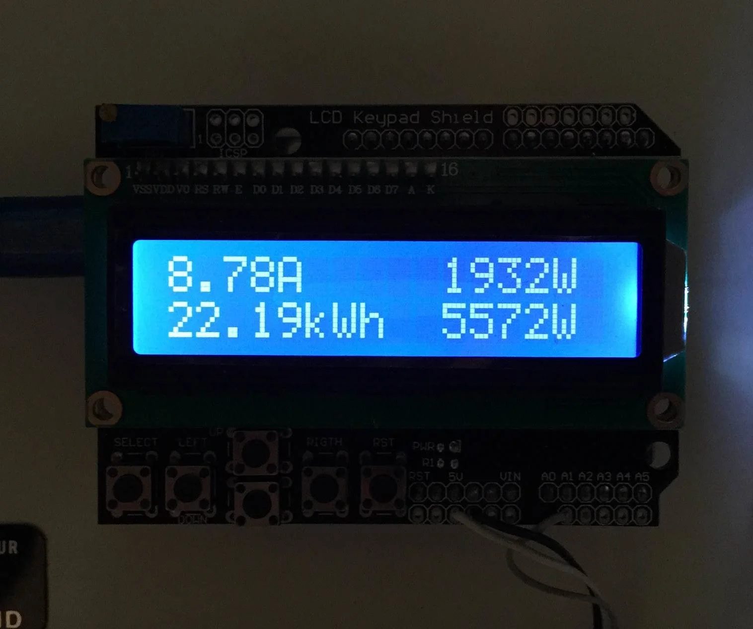
Testing the System
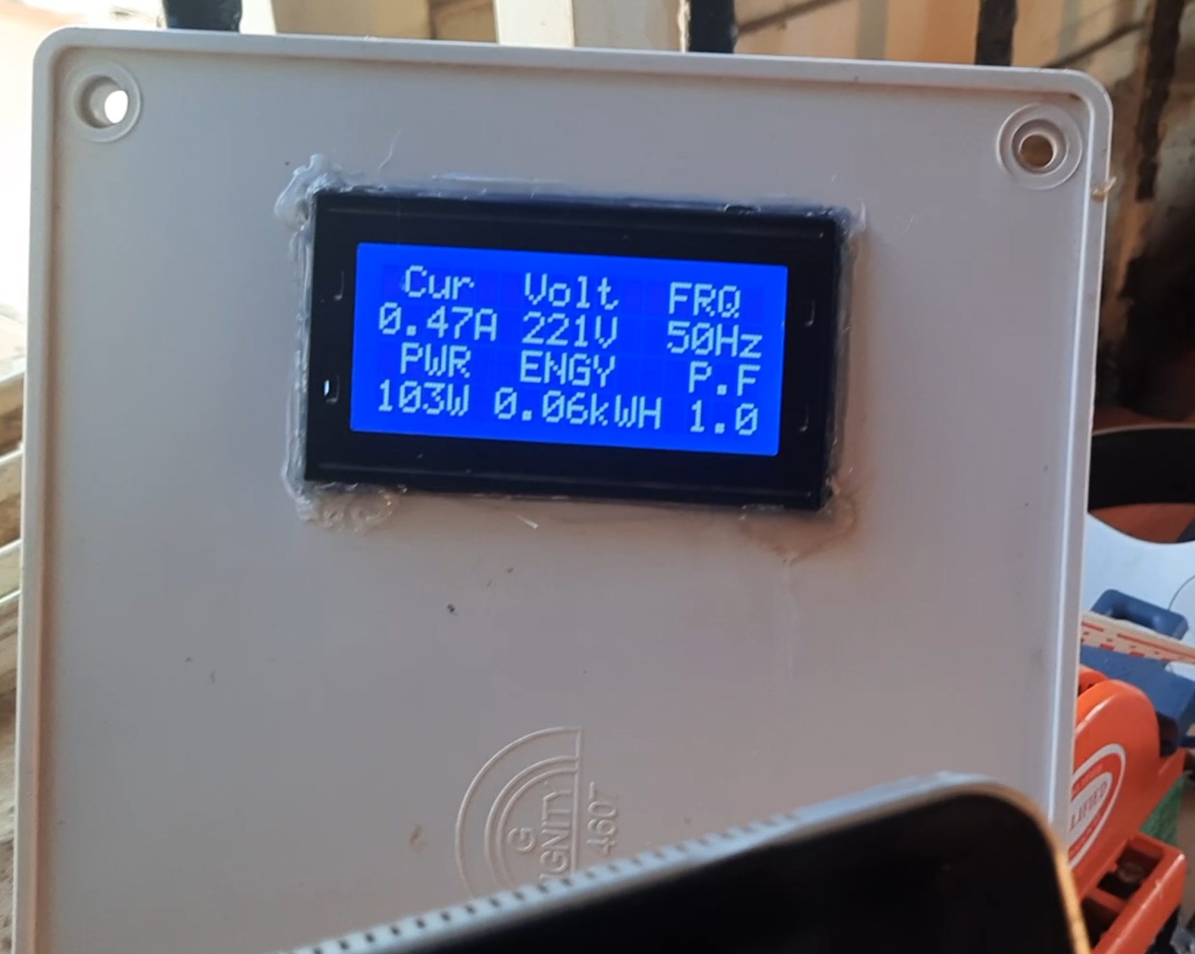
The successful uploading of the Arduino code to the microcontroller gave us that result as shown in the image above. Additionally, do the following below to ensure that the project worked as designed:
- Ensure all connections are secure.
- Power up the system and check if the sensors provide accurate readings.
- Calibrate the sensors if necessary.
Advanced Features for Your Energy Monitor
12. Adding IoT Functionality
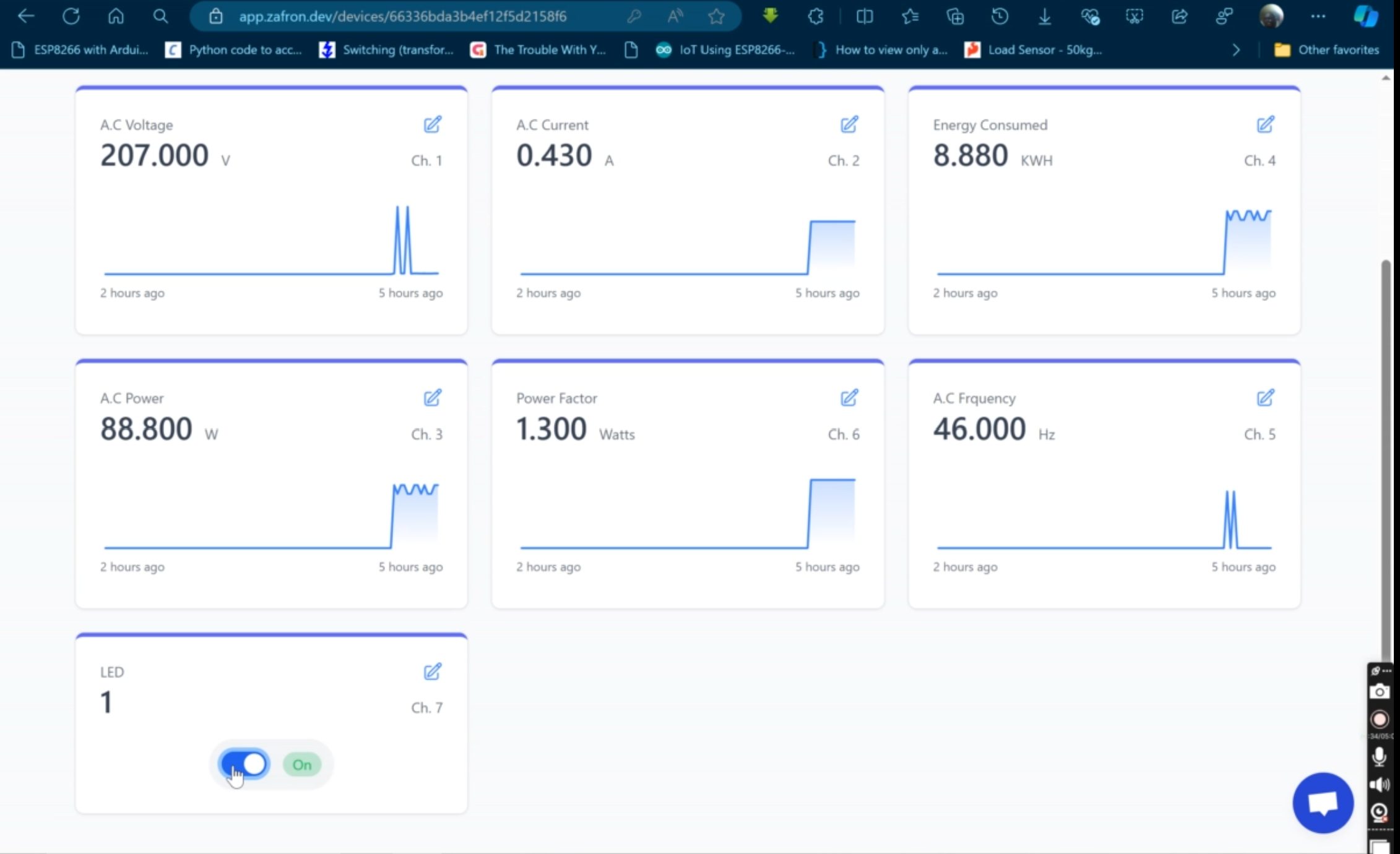
With the help of internet access, we sent the data on though ESP-01 module to Zafron IoT cloud platform. And this can be viewed on any phone or computer. We can monitor the energy readings that is being consumed by the appliances connected on the design.
Data Logging
Store historical energy usage data on an SD card or send it to a cloud database. This allows you to track long-term trends and patterns.
Alerts and Notifications
Set up alerts to notify you when energy consumption exceeds a certain threshold. This can be done using IoT platforms or even SMS modules.
Practical Applications
Identifying Energy Hogs
The system helps pinpoint devices that consume excessive power, enabling targeted energy-saving measures.
16. Promoting Sustainable Living
By monitoring energy usage, you can adopt habits that reduce your carbon footprint.
Educational Tool
This project isn’t just functional—it’s educational. It’s perfect for students and hobbyists looking to explore electronics and programming.
Challenges and How to Overcome Them
Accuracy Issues
Calibrate sensors carefully to ensure accurate readings. Use quality components to minimize errors.
Safety Concerns
Working with AC mains can be dangerous. Always follow safety precautions, such as using insulated tools and wearing gloves.
Data Overload
Too much data can be overwhelming. Focus on displaying key metrics like voltage, current, and energy usage.
Tips for Success
Start Simple
Begin with a basic setup before adding advanced features like IoT integration.
Double-Check Connections
Loose connections can lead to errors or malfunctions. Test the circuit thoroughly before powering it up.
Leverage Online Resources
The Arduino community is vast. If you’re stuck, forums and tutorials can be lifesavers.
Conclusion: Empower Your Energy Management
Building a home energy monitoring system using Arduino is a rewarding project. Not only does it save you money, but it also promotes a sustainable lifestyle and enhances your technical skills. With a little effort and creativity, you can create a system that tracks, analyzes, and helps optimize your energy usage.
So why wait? Start your journey to smarter energy management today. Your wallet—and the planet—will thank you!
Call to Action
Did this guide inspire you to create your own energy monitor? Share your thoughts or ask questions in the comments below. Let’s discuss and innovate together!
FAQs
1. How accurate is an Arduino-based energy monitor?
Accuracy depends on the quality of sensors and proper calibration. With good components, you can achieve reasonably precise readings.
2. Can I use this system for solar energy monitoring?
Yes, you can monitor energy generated by solar panels by connecting sensors to the system.
3. How much does it cost to build this project?
The cost varies based on the components used but typically ranges between $20 and $50.
4. Is it safe to work with AC mains in this project?
Safety is critical. Use insulated tools, follow guidelines, and consult professionals if unsure about handling high-voltage circuits.
5. Can I add voice commands to control the system?
Yes, integrating a voice module like the Arduino-compatible EasyVR can enable voice control features.