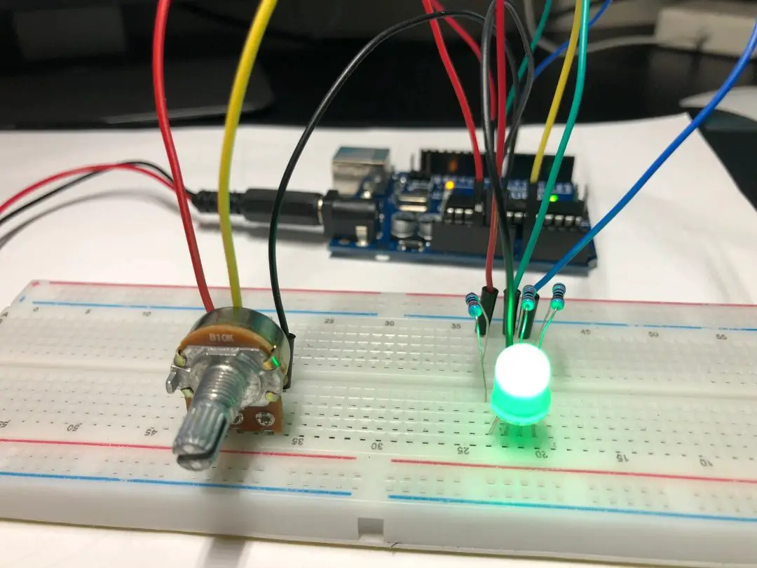
Think RGB LED Controller, imagine creating a mesmerizing light show with a simple turn of a knob. Sounds magical, right? With an RGB LED, potentiometers, and an Arduino, you can control colors dynamically, blending red, green, and blue to make almost any shade. This project is perfect for beginners and a fun introduction to how electronics and programming come together to create something visually stunning.

In this guide, we’ll explore how to build an RGB LED controller using potentiometers and an Arduino, walking through every detail to ensure your success.
What is an RGB LED?
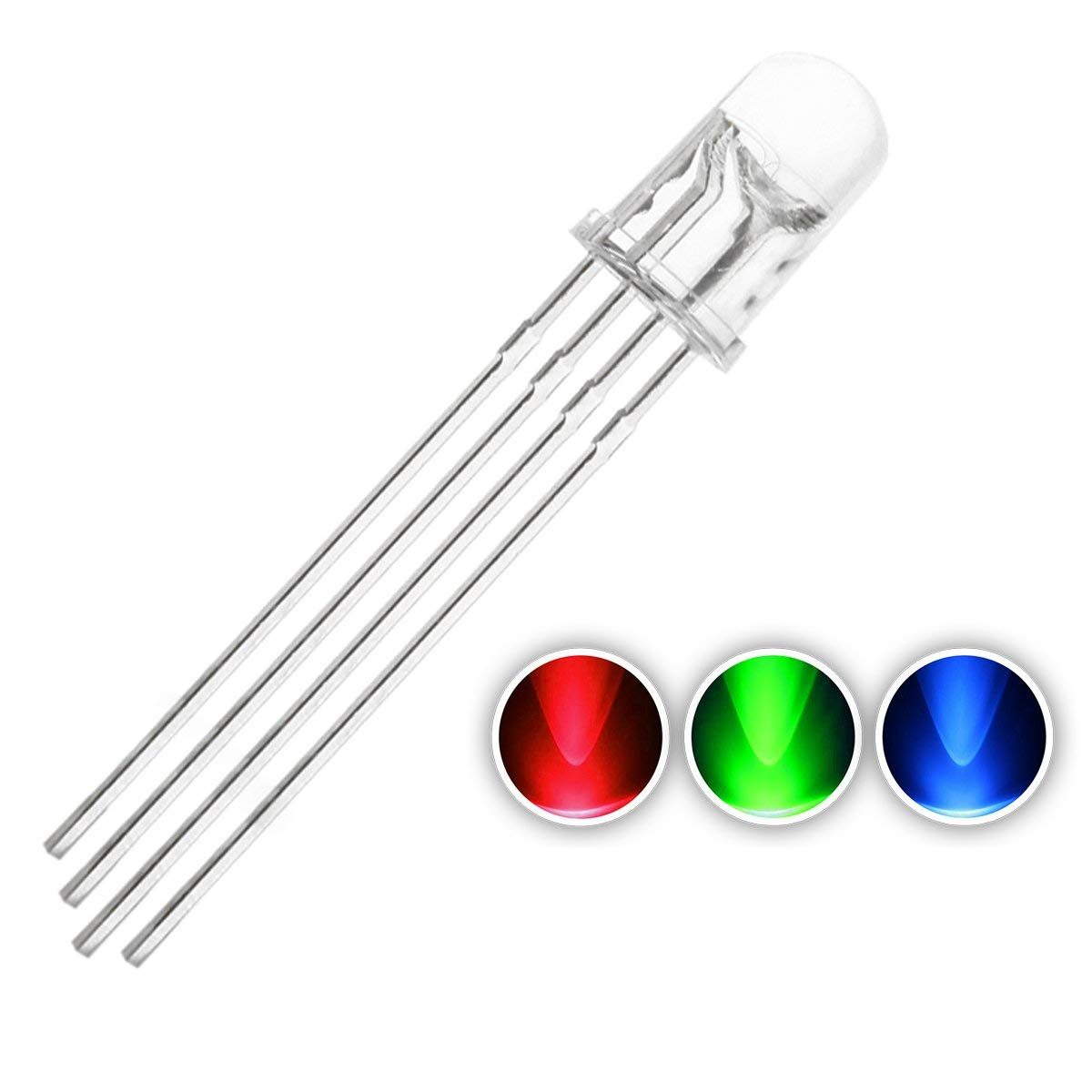
RGB LEDs are special light-emitting diodes that combine red, green, and blue lights into a single package. By adjusting the intensity of each color, you can create a wide spectrum of colors. It’s like mixing paint but with light!
How Do RGB LEDs Work?

RGB LEDs have four pins:
- Common cathode (or anode): Connects to GND (or 5V).
- Red pin: Controls the red component.
- Green pin: Controls the green component.
- Blue pin: Controls the blue component.
By sending a PWM signal to each color pin, you control the brightness of that color, creating custom hues.
Read Also Automatic Plant Watering Project With Smart Phone Control
What is a Potentiometer?

A potentiometer, or “pot,” is a variable resistor. Think of it as a volume knob for electronics—it adjusts the amount of electrical current flowing through a circuit. In this project, pots allow you to control the brightness of each LED color individually.
Components You’ll Need

Here’s a shopping list for your RGB LED controller project:
- Arduino board (Arduino Uno)
- RGB LED
- 3 potentiometers
- 3 resistors (220Ω)
- Breadboard
- Jumper wires
- USB cable (to connect Arduino to your computer)
Building the Circuit

Step 1: Connect the RGB LED
- Identify the common cathode (or anode) pin on your RGB LED.
- Connect it to the GND (or 5V) pin on the Arduino using a jumper wire.
- Connect the red, green, and blue pins to the breadboard.
Step 2: Add Resistors
Attach a 220Ω resistor to each color pin of the RGB LED. This prevents the LED from drawing too much current, which could damage it.
Step 3: Connect the Potentiometers
- Place the three potentiometers on the breadboard.
- Connect the middle pin of each pot to an analog input pin on the Arduino (e.g., A0, A1, A2).
- Connect one outer pin of each pot to 5V and the other to GND.
Step 4: Connect the RGB Pins to PWM
- Use jumper wires to connect the red, green, and blue pins of the LED to PWM-capable pins on the Arduino (e.g., pins 9, 10, and 11).
Writing the Arduino Code
Here’s the code you’ll need to bring your RGB controller to life:
int redPin = 9;    // PWM pin for red
int greenPin = 10; // PWM pin for green
int bluePin = 11;  // PWM pin for blue
int redPot = A0;   // Potentiometer for red
int greenPot = A1; // Potentiometer for green
int bluePot = A2;  // Potentiometer for blue

void setup() {
  pinMode(redPin, OUTPUT);
  pinMode(greenPin, OUTPUT);
  pinMode(bluePin, OUTPUT);
}

void loop() {
  int redValue = analogRead(redPot) / 4;    // Scale 10-bit to 8-bit
  int greenValue = analogRead(greenPot) / 4;
  int blueValue = analogRead(bluePot) / 4;

  analogWrite(redPin, redValue);
  analogWrite(greenPin, greenValue);
  analogWrite(bluePin, blueValue);

  delay(10); // Smooth updates
}
How Does the Code Work?
analogRead(): Reads the potentiometer value (0–1023).- Division by 4: Scales the 10-bit value to 8-bit (0–255) for PWM output.
analogWrite(): Sends the PWM signal to the RGB pins, adjusting brightness.
Uploading the Code
- Connect your Arduino to your computer with a USB cable.
- Open the Arduino IDE and paste the code.
- Select your board and port under the Tools menu.
- Click the Upload button.
Your RGB LED should now change colors as you turn the potentiometers.
Experimenting with Colors
Primary Colors
- Turn only the red potentiometer for pure red light.
- Similarly, adjust green or blue for their respective colors.
Secondary Colors
- Mix red and green to create yellow.
- Combine blue and green for cyan.
- Blend red and blue to make magenta.
Custom Shades
Subtle adjustments to all three pots allow you to create unique shades.
Applications of an RGB LED Controller
This project isn’t just a learning exercise—it’s the foundation for creative applications like:
- Mood lighting: Create ambiance with customizable colors.
- Smart home decor: Integrate with IoT for remote control.
- Visual feedback: Use as indicators in more advanced projects.
Troubleshooting Tips
The LED Doesn’t Light Up
- Double-check your connections.
- Ensure the correct resistor value (220Ω).
The Colors Don’t Change Smoothly
- Ensure the potentiometers are connected to the correct pins.
- Check the delay value in the code; too low can cause flickering.
The Arduino Won’t Upload the Code
- Verify the correct board and port are selected in the Arduino IDE.
- Ensure no other applications are using the COM port.
Scaling Up the Project
Once you’ve mastered the basics, take your RGB LED controller to the next level:
Add a Button
Include a push button to toggle between preset color modes or effects.
Use a Rotary Encoder
For precise control, replace the potentiometers with rotary encoders.
Control with a Smartphone
Integrate Bluetooth or Wi-Fi to adjust colors from your phone using apps like RemoteXY.
Why You Should Try This Project
Learning to control an RGB LED with potentiometers and Arduino isn’t just fun—it’s incredibly rewarding. You’re combining fundamental skills like circuit design, programming, and problem-solving. Plus, you get to watch your ideas light up—literally!
Conclusion
Building an RGB LED controller with potentiometers and Arduino is a fantastic project for anyone looking to dive into the world of electronics and programming. It’s simple, customizable, and opens the door to countless creative possibilities.
Ready to create your light show? Gather your components, fire up your Arduino, and let your imagination shine!
FAQs
1. Can I use a common anode RGB LED instead of a common cathode?
Yes, you can. Just connect the common anode to 5V and adjust your code accordingly.
2. Do I need resistors for all three LED pins?
Yes, using resistors for each pin is crucial to limit current and protect your RGB LED.
3. Can I use other input devices instead of potentiometers?
Absolutely! Try using light sensors, buttons, or even a joystick for more interactive controls.
4. What happens if I connect the LED without resistors?
Without resistors, the LED could draw too much current and burn out, damaging both the LED and your Arduino.
5. How can I make the colors change automatically?
Modify the code to include a loop that gradually changes the PWM values for each color pin. This creates an automated color-fading effect.