Traffic lights are an essential part of modern traffic management, ensuring the smooth flow of vehicles and pedestrian safety. But have you ever wondered how these systems work? Simulating a traffic signal using LEDs and an Arduino is an exciting project for beginners and enthusiasts looking to explore the world of electronics and programming. In this tutorial guide, we’ll take a deep dive into creating your own traffic light system, step by step.
Introduction: Why Simulate a Traffic Signal?
Creating a simulated traffic light system is not just a fun DIY project—it’s also highly educational. It introduces you to key concepts in programming, electronics, and logic design. Plus, it’s an excellent stepping stone for understanding real-world automation systems.
Whether you’re a student, hobbyist, or someone exploring Arduino projects for the first time, this simulation is a rewarding experience. Let’s light up the learning process!
Understanding Traffic Light Systems
The Purpose of Traffic Lights
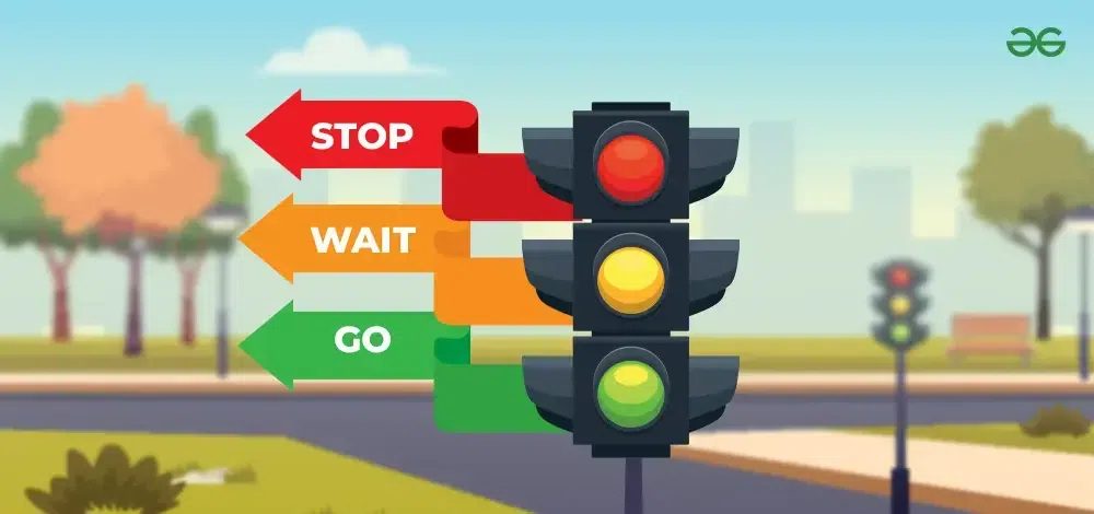
Traffic lights manage vehicle and pedestrian flow, reducing accidents and congestion. The standard system includes three lights:
- Red: Stop.
- Yellow: Prepare to stop.
- Green: Go.
The Logic Behind Traffic Signals
Traffic lights operate on pre-set timers or sensors to ensure vehicles and pedestrians alternate access to intersections. Simulating this system involves replicating the timing and sequence of light changes.
Components Required for the Project
Before you start, gather the following components:
- Arduino Uno: The brain of the project.
- LEDs (Red, Yellow, Green): Represent traffic lights.
- 220-ohm Resistors: Protect LEDs from excessive current.
- Breadboard: For circuit prototyping.
- Jumper Wires: To connect components.
- USB Cable: To upload the code to the Arduino.
Project Overview
In this project, we’ll simulate a simple traffic light sequence:
- Red LED on for 5 seconds.
- Yellow LED on for 2 seconds.
- Green LED on for 5 seconds.
The cycle will repeat continuously, mimicking a real-world traffic light system.
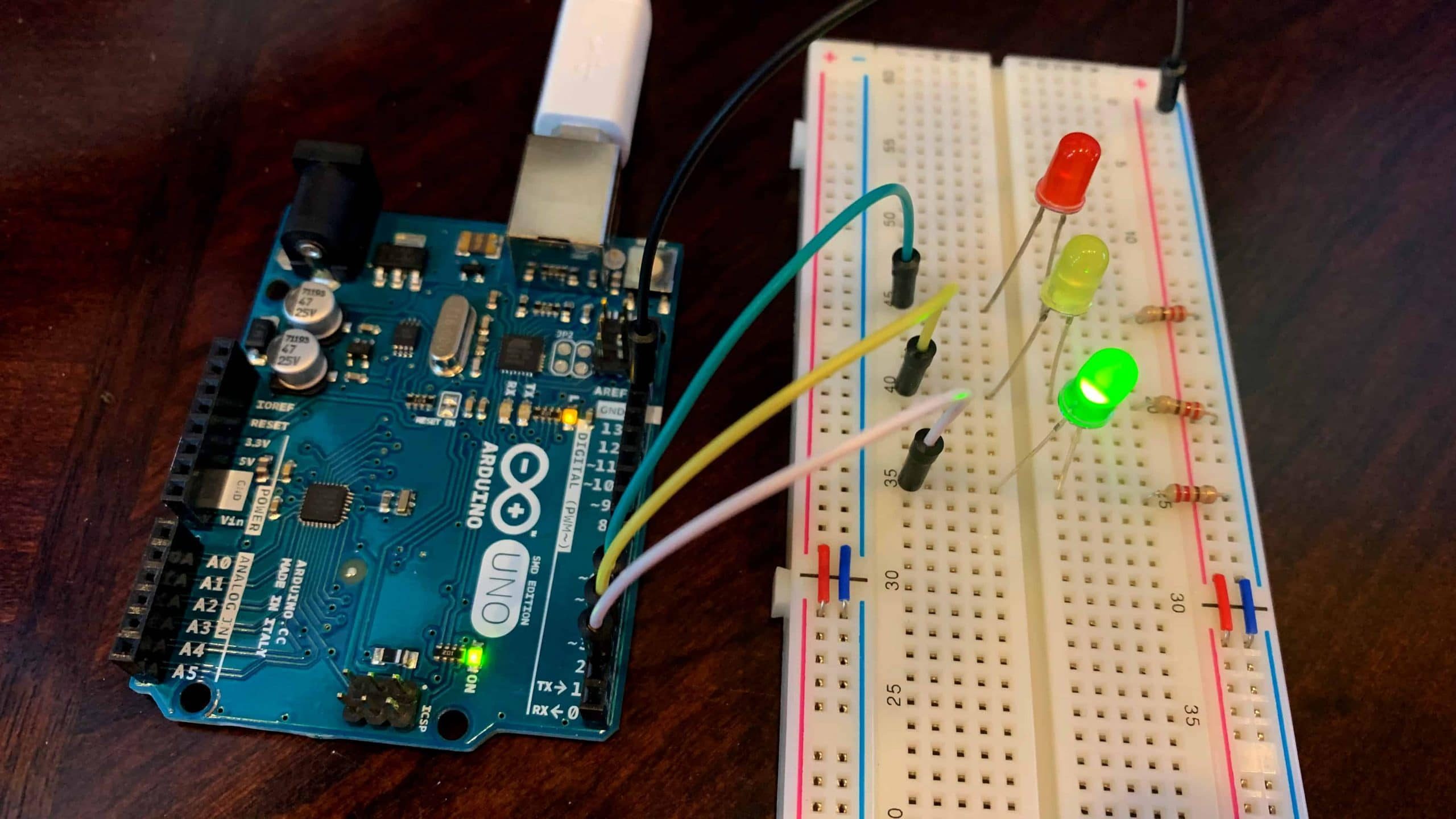
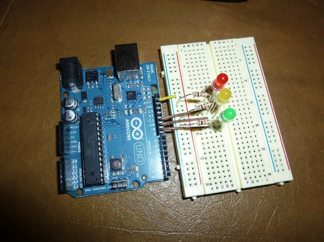
Setting Up the Circuit
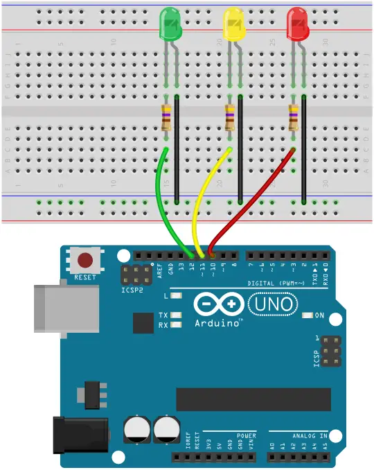
Step 1: Connect the LEDs
- Place the red, yellow, and green LEDs on the breadboard.
- Connect each LED’s longer leg (anode) to a digital pin on the Arduino (e.g., pins 8, 9, and 10).
Step 2: Add Resistors
- Connect a 220-ohm resistor to the shorter leg (cathode) of each LED.
- Attach the other end of the resistor to the GND rail on the breadboard.
Step 3: Complete the Connections
- Use jumper wires to link the GND rail on the breadboard to the GND pin on the Arduino.
- Ensure all connections are secure and match your circuit diagram.
Read Also How to Design A Remote Health Monitoring System with ESP32, LoRa, & Thingspeak
Writing the Arduino Code
Step 1: Open Arduino IDE
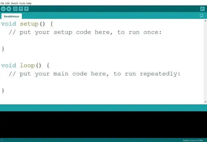
Download and install the Arduino IDE if you haven’t already. Open a new sketch.
Step 2: Define the Pins
int redLED = 8;
int yellowLED = 9;
int greenLED = 10;
Step 3: Setup Function
void setup() {
  pinMode(redLED, OUTPUT);
  pinMode(yellowLED, OUTPUT);
  pinMode(greenLED, OUTPUT);
}
Step 4: Loop Function
void loop() {
  digitalWrite(redLED, HIGH);   // Turn on red LED
  delay(5000);                 // Wait 5 seconds
  digitalWrite(redLED, LOW);    // Turn off red LED

  digitalWrite(yellowLED, HIGH); // Turn on yellow LED
  delay(2000);                  // Wait 2 seconds
  digitalWrite(yellowLED, LOW);  // Turn off yellow LED

  digitalWrite(greenLED, HIGH);  // Turn on green LED
  delay(5000);                  // Wait 5 seconds
  digitalWrite(greenLED, LOW);   // Turn off green LED
}
Step 5: Upload the Code
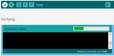
Connect your Arduino to the computer using a USB cable. Click the upload button in the IDE to transfer the code.
Testing Your Traffic Light System
Once the code is uploaded, the LEDs should begin cycling through the traffic light sequence. Observe how the lights change and adjust the timing in the code if necessary.
Expanding the Project
Here are some things you can include in this simulation to improve on the project design.
Adding a Pedestrian Crossing
Include additional LEDs and a button for pedestrians to signal their turn to cross.
Implementing Sensors
Use light-dependent resistors (LDRs) or ultrasonic sensors to simulate real-world traffic-responsive lights.
Simulating a Four-Way Intersection
Expand the project to include multiple sets of traffic lights, adding complexity and realism.
Learning Outcomes
This project teaches:
- Basic Circuit Design: Understanding how components like LEDs and resistors work together.
- Arduino Programming: Writing and uploading code to control hardware.
- Problem-Solving Skills: Debugging and refining your system for better performance.
Troubleshooting Tips
1. LED Not Lighting Up
- Check the connections for loose wires or incorrect pin assignments.
- Ensure the resistor value is appropriate.
2. Code Not Uploading
- Verify that the correct COM port is selected in the Arduino IDE.
- Ensure the Arduino drivers are installed.
3. Timing Issues
- Adjust the
delay()values in the code for smoother transitions.
Applications of Traffic Light Simulations
Education
Traffic light systems are great for teaching logic and programming to beginners.
Prototype Development
Engineers and designers can use simulations to prototype traffic management solutions.
STEM Projects
This project aligns with STEM learning objectives, fostering innovation and creativity.
Conclusion
Simulating a traffic light system using LEDs and Arduino is a rewarding project that combines creativity with practical skills. Whether you’re a beginner or a seasoned maker, this project is an excellent way to dive into the world of electronics and programming. With endless possibilities for expansion, the traffic light simulation is more than just a learning experience—it’s a stepping stone to understanding and creating more complex systems.
FAQs
1. What is the main purpose of this project?
To simulate a basic traffic light system, teaching circuit design and Arduino programming.
2. Can I use other types of LEDs for this project?
Yes, as long as you adjust the resistor values and connections appropriately.
3. How can I make the system more realistic?
Add sensors or expand the project to include pedestrian crossings and multiple intersections.
4. Is this project suitable for beginners?
Absolutely! It’s simple enough for beginners yet offers opportunities for advanced modifications.
5. Can I control the traffic lights with a smartphone?
Yes, integrating a Bluetooth module allows for smartphone control, adding another layer of interactivity.