Imagine walking into a room, and the lights turn on automatically. Or picture a plant whose LEDs light up to indicate it needs watering. These are just a few examples of how sensors and LEDs controlled by Arduino can transform everyday life. In this guide, we’ll explore how you can pair sensors with LEDs and Arduino to create interactive and responsive systems.
By the end of this article, you’ll not only understand the basics but also be ready to implement exciting projects using sensors to control LEDs.
Why Combine Sensors, LEDs, and Arduino?
Sensors and LEDs, when controlled by Arduino, allow you to:
- Visualize Data: LEDs can represent sensor readings (e.g., temperature or proximity).
- Create Feedback Systems: Sensors trigger LEDs as indicators for specific conditions.
- Build Automation Projects: Think of systems that react to light, sound, or motion.
This trio of components forms the backbone of many real-world applications, from smart homes to robotics.
Read Also How to Build an IoT Pulse Rate Monitoring with ESP32 Arduino
What You’ll Need (Components)
Here’s a list of essentials to get started:
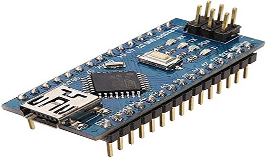
- Arduino Board (e.g., Uno, Nano, or Mega) We used the Arduino Uno for these examples here.
- LEDs (standard or RGB)
- Sensors (light, temperature, motion, or others)
- Resistors (220-ohm for LEDs, others depending on the sensor)
- Breadboard
- Jumper Wires
- USB Cable
Types of Sensors to Use With LEDs
1. Light Sensors (Photoresistors or LDRs)
- Detect ambient light levels.
- Control LEDs to turn on in the dark or off in bright light.
2. Temperature Sensors (LM35 or DHT11)
- Monitor temperature and trigger LEDs based on predefined thresholds.
3. Motion Sensors (PIR Sensors)
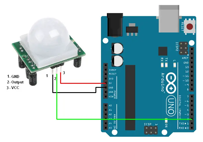
- Detect movement and activate LEDs.
- Commonly used in security or automation systems.
4. Sound Sensors
- React to claps or other noises to turn LEDs on or off.
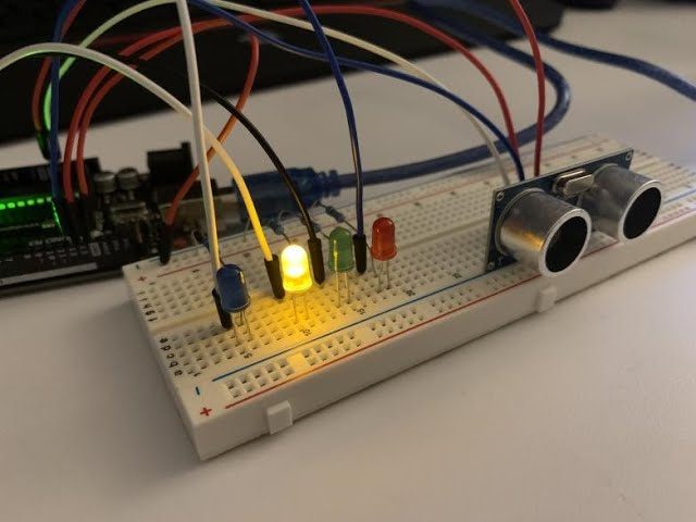
5. Proximity Sensors (Ultrasonic Sensors)
- Measure distance and control LED brightness or blinking based on proximity.
Building the Circuit
Let’s create a basic setup where a light sensor controls an LED.
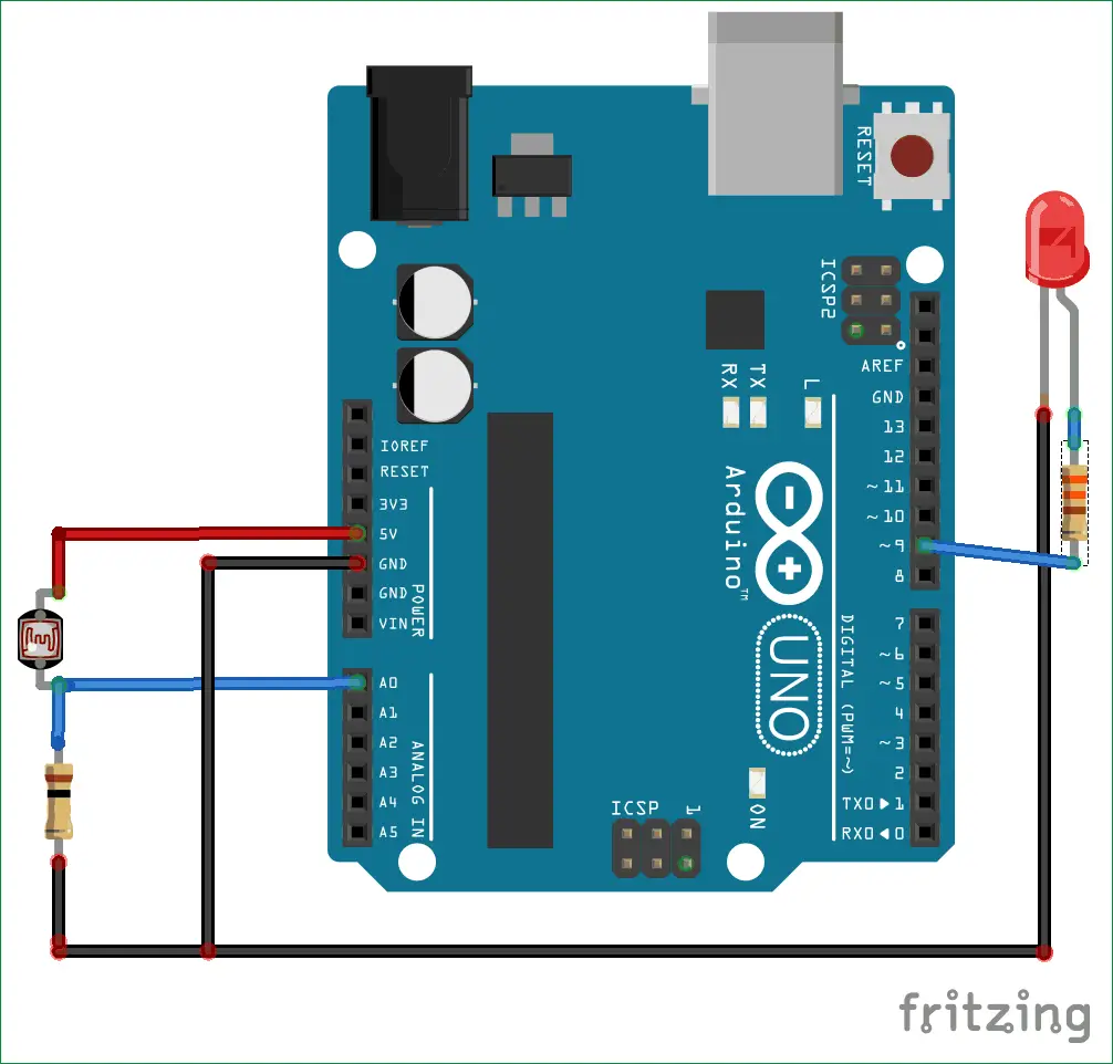
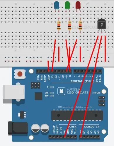
Step 1: Light Sensor and LED Wiring
- Place the LED on the breadboard.
- Connect the anode (long leg) to pin 9 via a 220-ohm resistor.
- Connect the cathode (short leg) to GND.
- Attach the LDR (light-dependent resistor) to the breadboard.
- Connect one leg of the LDR to 5V and the other to A0 (analog pin).
- Add a 10k-ohm pull-down resistor between the LDR’s second leg and GND.
Writing the Arduino Code
Here’s how to program your Arduino to control the LED based on light levels.
Code for Light Sensor and LED
const int ledPin = 9;       // LED connected to pin 9
const int sensorPin = A0;   // Light sensor connected to A0
int sensorValue = 0;        // Variable to store sensor value

void setup() {
  pinMode(ledPin, OUTPUT);
  Serial.begin(9600);       // For debugging
}

void loop() {
  sensorValue = analogRead(sensorPin);   // Read sensor value
  Serial.println(sensorValue);          // Print value to monitor

  if (sensorValue < 500) {              // Adjust threshold as needed
    digitalWrite(ledPin, HIGH);         // Turn LED on
  } else {
    digitalWrite(ledPin, LOW);          // Turn LED off
  }
}
How the Code Works
- analogRead(): Reads the analog value from the light sensor.
- if Statement: Compares the sensor value to a threshold (500 in this case).
- digitalWrite(): Turns the LED on or off based on the sensor reading.
Testing the Circuit
- Upload the code to your Arduino board.
- Cover the LDR to simulate darkness. The LED should light up.
- Expose the LDR to bright light. The LED should turn off.
This simple interaction demonstrates how sensors can trigger LEDs.
Expanding the Project
1. Temperature-Controlled LEDs
Use a temperature sensor, using DHT11 sensor to control LEDs based on heat levels.
Code Example:
#include <DHT.h>
#define DHTPIN 2 // Sensor pin
#define DHTTYPE DHT11 // Type of sensor
DHT dht(DHTPIN, DHTTYPE);
const int ledPin = 9;
int temp = 0;
void setup() {
pinMode(ledPin, OUTPUT);
dht.begin();
Serial.begin(9600);
}
void loop() {
temp = dht.readTemperature();
Serial.println(temp);
if (temp > 30) { // Turn LED on if temperature exceeds 30°C
digitalWrite(ledPin, HIGH);
} else {
digitalWrite(ledPin, LOW);
}
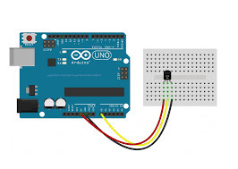
}2. Motion-Sensing LEDs
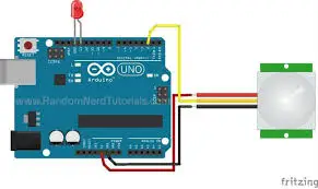
Replace the light sensor with a PIR motion sensor to activate LEDs when movement is detected.
The Arduino Code
int led = 13;                // the pin that the LED is atteched to
int sensor = 2;              // the pin that the sensor is atteched to
int state = LOW;             // by default, no motion detected
int val = 0;                 // variable to store the sensor status (value)

void setup() {
  pinMode(led, OUTPUT);      // initalize LED as an output
  pinMode(sensor, INPUT);    // initialize sensor as an input
  Serial.begin(9600);        // initialize serial
}

void loop(){
  val = digitalRead(sensor);   // read sensor value
  if (val == HIGH) {           // check if the sensor is HIGH
    digitalWrite(led, HIGH);   // turn LED ON
    delay(100);                // delay 100 milliseconds

    if (state == LOW) {
      Serial.println("Motion detected!");
      state = HIGH;       // update variable state to HIGH
    }
  }
  else {
      digitalWrite(led, LOW); // turn LED OFF
      delay(200);             // delay 200 milliseconds

      if (state == HIGH){
        Serial.println("Motion stopped!");
        state = LOW;       // update variable state to LOW
    }
  }
}
Real-World Applications
- Smart Lighting: Automate lights in homes or offices based on ambient light or motion.
- Environmental Monitoring: Use temperature or humidity sensors with LEDs as visual indicators.
- Interactive Displays: Create art installations that react to touch, sound, or motion.
- Proximity Alerts: Build systems to warn when objects are too close.
Troubleshooting Tips
LED Not Responding:
- Check wiring, especially the LED’s polarity.
- Ensure the resistor is connected.
Inconsistent Sensor Readings:
- Verify connections and power supply.
- Shield sensors from interference.
Code Errors:
- Double-check pin assignments in the code.
- Use the Serial Monitor for debugging.
Advanced Ideas
RGB LED Control
Use sensor inputs to change the color of an RGB LED dynamically.
IoT Integration
Send sensor data to an IoT platform and control LEDs remotely using an ESP8266 module.
Data Logging
Log sensor data while using LEDs as real-time indicators for certain thresholds.
Safety Precautions
- Use appropriate resistors to prevent damage to LEDs or sensors.
- Avoid exposing sensors to extreme conditions unless they are rated for it.
- Disconnect power while making changes to the circuit.
Conclusion
Controlling LEDs with sensors and Arduino opens up a world of possibilities for interactive and automated systems. Whether you’re monitoring light levels, detecting motion, or responding to temperature changes, this project serves as a stepping stone to more advanced designs.
So, grab your sensors, LEDs, and Arduino, and let your creativity shine. The only limit is your imagination!
FAQs
1. Can I use multiple sensors in one project?
Yes, you can use multiple sensors with different Arduino pins, but ensure proper coding and wiring.
2. How do I adjust the sensitivity of the sensors?
Sensitivity can often be adjusted by changing the sensor’s position, threshold in the code, or adding a potentiometer.
3. What is the difference between analog and digital sensors?
Analog sensors provide a range of values, while digital sensors provide binary outputs (HIGH or LOW).
4. Can I control an RGB LED with a single sensor?
Absolutely! Use the sensor’s readings to control individual colors (red, green, blue) via PWM pins.
5. Is it possible to control LEDs with wireless sensors?
Yes, with modules like Bluetooth, LoRa, or Zigbee, you can wirelessly send sensor data to control LEDs.