Introduction
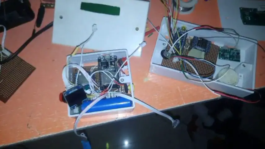
Remote health monitoring systems have grown in significance in the quickly developing field of the Internet of Things. This project builds a system that can measure human body temperature, skin humidity, and pulse rate by utilizing the capabilities of the digital humidity and temperature sensor module and pulse sensor module as well as an ESP32 development board, two LoRa modules, and the Thingspeak IoT platform for remote viewing. In addition to being published to an internet platform for convenient access and monitoring, the data is wirelessly transferred to a distant receiver using the Long Range (LoRa) modules.
Innovative systems that may remotely monitor patient health have been made possible by the integration of IoT in healthcare. The main goal of this project to build a system that employs an ESP32 and DHT11 sensor to measure temperature, humidity, and pulse rate hasn’t changed. But also a remote receiver receives the data via LoRa and shows the readings on an LCD. Furthermore, the ESP32 is configured to establish a WiFi connection and transmit the data to Thingspeak IoT Cloud, enabling online real-time monitoring.
Components Parts Required for Remote health Monitoring Design
To build this project, the following components are required:
- ESP32 development board
- DHT11 digital temperature and humidity sensor
- Pulse sensor module
- LoRa Sx1278 modules (transmitter and receiver)
- Arduino Nano
- LCD display 1604
- Breadboard and jumper wires
- Rechargeable Power supply (LiPo battery)
- WiFi network with internet access
Explanation of the Uses of the Components
ESP32 Board

The ESP32 is a powerful microcontroller with built-in WiFi and Bluetooth capabilities, making it an excellent choice for IoT projects. It has multiple GPIO pins, supports various communication protocols, and has a low power consumption mode, making it suitable for battery-operated devices.
DHT11 Sensor

The DHT11 sensor is a low-cost digital sensor for measuring temperature and humidity. It provides a calibrated digital output and is easy to interface with any microcontroller. We had to use this with a 10kilo-Ohm resistor.
Pulse Sensor

The pulse sensor measures the heart rate by detecting changes in light absorption in the blood vessels. It is commonly used in wearable health devices and can be easily integrated into an Arduino or ESP32 project.
LoRa Sx1278 Modules

These LoRa (Long Range) modules are used for long-distance wireless communication. They operate in the unlicensed ISM bands and are known for their low power consumption and ability to transmit data over long distances (up to 10 km in open areas).
Arduino Nano
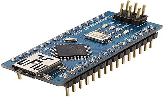
The Arduino Nano is a compact version of the Arduino Uno and is often used in projects where space is limited. It has fewer GPIO pins than the Uno but is more than sufficient for this project.
LCD Module
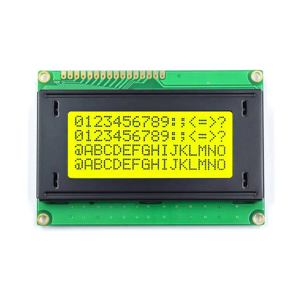
The LCD display will be used to show the temperature, humidity, and pulse rate values received by the Arduino Nano. The display is a 16×4 version, this depended on the our preference.
Android Platform Based Temperature Monitoring Design for Poultry Farms
Smart Window Automation: Arduino-Based System for Rain, Smoke, and Gas Detection
DIY Remote-Controlled Fan Using Arduino: A Step-by-Step Guide
Step-by-Step Guide to Building the System
The Circuit Diagram of the Transmitter (ESP32) Side

Step 1: Connecting the DHT11 Sensor
- Connect the VCC pin of the DHT11 to the 3.3V pin of the ESP32.
- Connect the GND pin of the DHT11 to the GND of the ESP32.
- Connect the DATA pin of the DHT11 to digital GPIO pin 4 of the ESP32 ( GPIO 4).
Step 2: Connecting the Pulse Sensor
- Connect the VCC pin of the pulse sensor to the 3.3V pin of the ESP32.
- Connect the GND pin of the pulse sensor to the GND of the ESP32.
- Connect the signal pin of the pulse sensor to an analog input pin 34 of the ESP32 (GPIO 34).
Step 3: Connecting the LoRa Module
- Connect the VCC pin of the LoRa module to the 3.3V pin of the ESP32.
- Connect the GND pin of the LoRa module to the GND of the ESP32.
- Connect the SCK, MISO, MOSI, and NSS pins of the LoRa module to the respective SPI pins on the ESP32 (SCK to GPIO 18, MISO to GPIO 19, MOSI to GPIO 23, and NSS to GPIO 5).
Programming the Transmitter Side
#include <WiFi.h>
#include <DHT.h>
#include <LoRa.h>
#include <ThingSpeak.h>

// Define pins and constants
#define DHTPIN 4
#define DHTTYPE DHT11
#define PULSE_PIN 34

DHT dht(DHTPIN, DHTTYPE);

// WiFi credentials
const char* ssid = "your_SSID";
const char* password = "your_PASSWORD";

// ThingSpeak settings
unsigned long myChannelNumber = YOUR_CHANNEL_NUMBER;
const char * myWriteAPIKey = "YOUR_WRITE_API_KEY";

WiFiClient client;

void setup() {
  Serial.begin(115200);
  dht.begin();

  // Initialize WiFi
  WiFi.begin(ssid, password);
  while (WiFi.status() != WL_CONNECTED) {
    delay(500);
    Serial.print(".");
  }
  Serial.println("WiFi connected");

  ThingSpeak.begin(client);

  // Initialize LoRa
  LoRa.begin(915E6);
}

void loop() {
  float temperature = dht.readTemperature();
  float humidity = dht.readHumidity();
  int pulseRate = analogRead(PULSE_PIN);

  // Send data via LoRa
  LoRa.beginPacket();
  LoRa.print(temperature);
  LoRa.print(",");
  LoRa.print(humidity);
  LoRa.print(",");
  LoRa.print(pulseRate);
  LoRa.endPacket();

  // Send data to ThingSpeak
  ThingSpeak.setField(1, temperature);
  ThingSpeak.setField(2, humidity);
  ThingSpeak.setField(3, pulseRate);
  ThingSpeak.writeFields(myChannelNumber, myWriteAPIKey);

  delay(2000);
}
We used the Arduino IDE to program the ESP32. We also installed the necessary libraries for the DHT11 sensor, pulse sensor, and LoRa communication. We wrote a sketch (Arduino Code) that reads the temperature, humidity, and pulse rate. The data should be formatted and sent via LoRa to the receiver.
Additionally, we programmed the ESP32 to connect to a WiFi network and send the data to Thingspeak.
Setting Up the Receiver (Arduino Nano) Side
The Circuit Diagram of the Receiver (Arduino Nano) Side

Step 1: Connecting the LoRa Module
- Connect the VCC pin of the LoRa module to the 5V pin of the Arduino Nano.
- Connect the GND pin of the LoRa module to the GND of the Arduino Nano.
- Connect the SCK, MISO, MOSI, and NSS pins of the LoRa module to the respective SPI pins on the Arduino Nano.
Step 2: Connect the LCD Display
- Connect the VCC pin of the LCD to the 5V pin of the Arduino Nano.
- Connect the GND pin of the LCD to the GND of the Arduino Nano.
- Connect the data pins according to the circuit diagram shown above.
Programming the Arduino Nano for the Receiver Side
#include <LoRa.h>
#include <Wire.h>
#include <LiquidCrystal_I2C.h>

LiquidCrystal_I2C lcd(0x27, 16, 2);

void setup() {
  Serial.begin(9600);
  lcd.begin();
  lcd.backlight();

  // Initialize LoRa
  LoRa.begin(915E6);
}

void loop() {
  int packetSize = LoRa.parsePacket();
  if (packetSize) {
    String receivedData = "";
    while (LoRa.available()) {
      receivedData += (char)LoRa.read();
    }
    Serial.println(receivedData);

    // Parse the received data
    int commaIndex1 = receivedData.indexOf(',');
    int commaIndex2 = receivedData.indexOf(',', commaIndex1 + 1);

    float temperature = receivedData.substring(0, commaIndex1).toFloat();
    float humidity = receivedData.substring(commaIndex1 + 1, commaIndex2).toFloat();
    int pulseRate = receivedData.substring(commaIndex2 + 1).toInt();

    // Display data on LCD
    lcd.setCursor(0, 0);
    lcd.print("Temp: " + String(temperature) + " C");
    lcd.setCursor(0, 1);
    lcd.print("Hum: " + String(humidity) + " %");
    lcd.setCursor(10, 1);
    lcd.print("Pulse: " + String(pulseRate));
  }
}
The above Arduino code used the I2C LCD module. You can modify the code to use the four wire type. You can see an example code of this here. And use the Arduino IDE to program the Arduino Nano. Don’t forget to the install the necessary libraries for LoRa communication and the LCD display. This sketch receives the data sent by the ESP32 via LoRa and displays it on the LCD.
Uploading Data to ThingSpeak
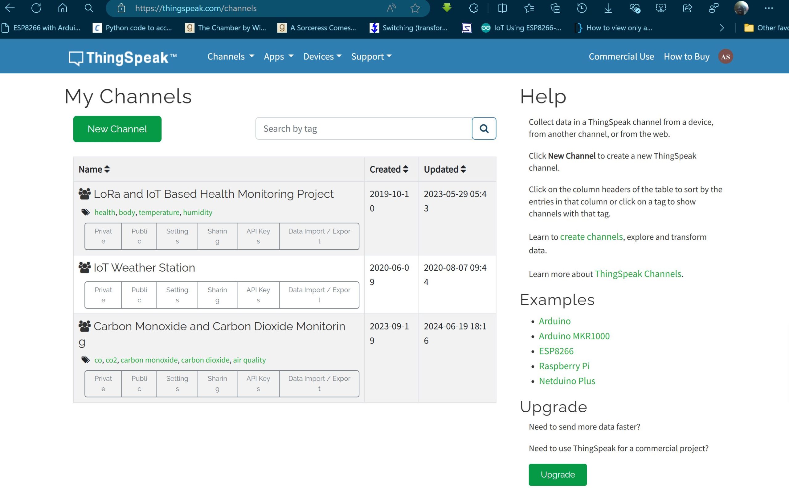
Step 1: Creating a Thingspeak Account
- By visiting the ThingSpeak website and we created an account. Once logged in, we created a new channel and set up the fields for temperature, humidity, and pulse rate.
Step 2: Configuring the ESP32
- We used the provided API key and channel ID in our ESP32 code to send data to Thingspeak. The data were displayed in real-time on our ThingSpeak dashboard.
Testing and Troubleshooting
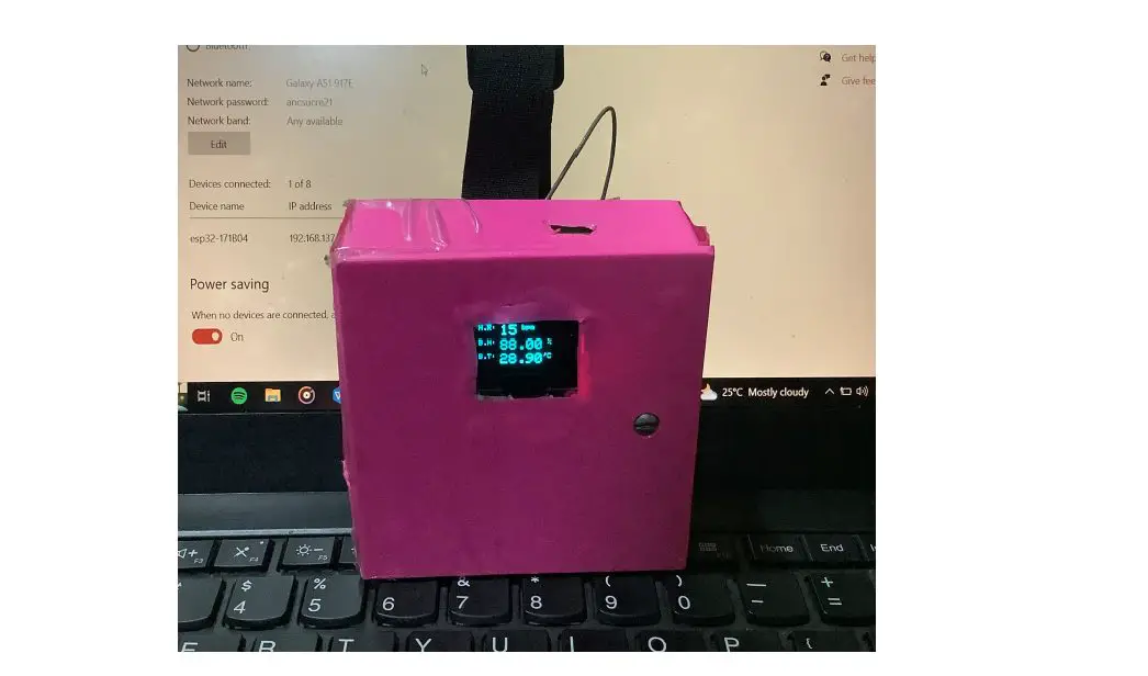
After building the system, it was essential to test each component. We tested the DHT11 sensor and ensured that the sensor was providing accurate temperature and humidity readings. Next, we tested the pulse sensor: we checked that the pulse sensor is correctly reading the pulse rate and displaying consistent values. And lastly, we tested the LoRa Modules and ensured that data is being transmitted and received correctly between the ESP32 board and the Arduino Nano board.
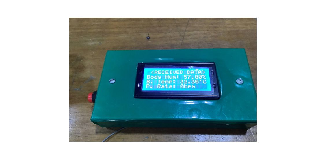
The receiver got all the data measured and sent across by the transmitter. And it is displayed here on this 2004 LCD screen as shown in the image above.
Conclusion
This project demonstrates the potential of IoT in healthcare by enabling remote monitoring of vital signs such as temperature, humidity, and pulse rate. By leveraging the ESP32’s WiFi capabilities and LoRa’s long-range communication, the system can transmit data over significant distances and upload it to the Thingspeak platform for real-time monitoring. Whether you’re a beginner or an experienced maker, this project is a great way to explore the intersection of IoT and healthcare.
Leave us a comment below to tell us how this tutorial helped you positively. We will be waiting eagerly to read from you.
FAQs
1. What is the purpose of using LoRa in this project?
LoRa is used in this project for long-range wireless communication. It allows the ESP32 to send data over long distances to the Arduino Nano, even in areas where WiFi coverage may be limited.
2. Can I use other sensors instead of the DHT11?
Yes, you can use other temperature and humidity sensors like the DHT22 or the BME280. However, you may need to modify the code slightly to accommodate the different sensor libraries.
3. Why do I need Thingspeak, and can I use another platform?
Thingspeak is used in this project to provide real-time monitoring and data storage in the cloud. You can use other IoT platforms like Adafruit IO, Blynk, or AWS IoT, but you’ll need to adjust the code to work with those platforms.
4. How far can the LoRa modules transmit data?
LoRa modules can transmit data up to 10 km in open areas, depending on the environment and antenna quality. However, the range may be shorter in urban or obstructed environments.
5. What are the power requirements for this project?
The ESP32, Arduino Nano, and LoRa modules can all be powered via USB or batteries. Ensure that your power supply provides sufficient voltage and current for all components, typically around 3.3V to 5V.
6. Is it possible to add more sensors to this system?
Yes, you can add more sensors, such as a blood oxygen sensor, to monitor additional health parameters. You’ll need to modify the code to read and transmit the data from these sensors.
7. How can I troubleshoot connectivity issues with the WiFi or LoRa modules?
Ensure that the correct credentials and settings are configured in your code for WiFi and LoRa. Check the wiring connections and verify that the modules are properly powered. Debugging tools like Serial Monitor can help identify issues during testing.
8. Can this project be expanded for multiple patients?
Yes, the project can be expanded to monitor multiple patients by assigning unique identifiers to each ESP32 unit and modifying the code to handle multiple data streams on the Thingspeak platform.
9. What are the main limitations of this project?
The primary limitations include the range of the LoRa modules in certain environments, potential interference with WiFi connectivity, and the accuracy of the DHT11 sensor compared to more advanced sensors.
10. How secure is the data transmission in this system?
LoRa communication is relatively secure, but if additional security is needed, you can implement encryption methods in the data transmission process. For WiFi and Thingspeak, standard encryption protocols (like HTTPS) help protect data integrity.