In today’s world, security is paramount, and technology has provided us with innovative ways to ensure that our homes and workplaces are secure. One such technology is RFID (Radio Frequency Identification), which is used in access control systems to regulate entry to secure areas. Imagine walking up to a door, swiping a card, and having it unlock instantly, only for authorized users. This project explores how you can build an RFID-based access control system using an Arduino, the MFRC522 reader, RFID cards, and a DC solenoid lock.
In this project design, we will create a security system where RFID tags are used to control access to a restricted area. The system can be designed to log entries and exits, and even integrate with a database to manage user permissions. Let’s dive into how this system works, how to build it step-by-step, and why RFID technology is such a game-changer for modern security.
What Is RFID?

Before we get into the nitty-gritty of the project, let’s understand what RFID technology is. RFID stands for Radio Frequency Identification, a technology that uses electromagnetic fields to automatically identify and track tags attached to objects. The RFID system comprises two main components: a reader and a tag. The reader emits a signal that powers the RFID tag, which then transmits data back to the reader. This data is usually a unique identifier that helps the system decide whether access should be granted or denied.
Our aim in this project is to ensure the RFID reader will be able to scan a tag (or RFID card), check if it is authorized, and then either unlock a door by activating a solenoid lock or keep the door locked if the tag is unauthorized.
Why Use RFID for Access Control?
RFID technology is widely used for access control systems because it is:
- Secure: The tags contain unique IDs that can be encrypted and difficult to clone.
- Contactless: There’s no need for physical contact between the tag and the reader.
- Fast: The access process is almost instantaneous, offering convenience for users.
- Scalable: RFID systems can manage multiple tags, making them suitable for large-scale applications.
Components Needed for an RFID-Based Access Control System
To build this project, you’ll need a few key components that work together to make the RFID-based access system function. Here’s a list of the required hardware and tools:
Arduino Uno

The Arduino Uno is the brain of the system, responsible for processing input from the RFID reader and controlling the solenoid lock. It reads the data from the RFID card and decides whether to unlock the door.
MFRC522 RFID Reader Module

The MFRC522 is a low-cost RFID module used for reading RFID tags. It operates at 13.56 MHz and communicates with the Arduino via the SPI interface. It is compact and suitable for embedded systems.
RFID Cards/Tags

These cards or tags store unique data that the RFID reader scans. The tags contain a unique identifier, which the system will match against pre-authorized tags stored in the Arduino’s memory.
DC Solenoid Lock

The solenoid lock serves as the locking mechanism for the door. When the right RFID card is scanned, the Arduino sends a signal to unlock the solenoid lock for a few seconds, granting access.
Relay Module/or TIP41C Transistor
A relay module is used to control the solenoid lock. Since the Arduino cannot provide enough current to drive the solenoid lock directly, the relay acts as a switch that controls the lock using external power.

You can also use TIP41C NPN transistor to get the same result by connecting it as a common emitter follower (See circuit diagram below). That way, you reduce cost and save time too.
Breadboard and Jumper Wires

For connecting the various components together and creating a prototype, you’ll need a breadboard and jumper wires.
12V Power Supply
The solenoid lock requires external power, typically 12V, which is supplied through a power adapter.
How RFID Access Control Systems Work (Flowchart)
Now that you have the components, let’s understand how the system functions:
- User swipes the RFID card at the reader.
- The reader scans the card’s unique identifier and sends it to the Arduino for processing.
- The Arduino checks the card’s ID against a list of authorized IDs stored in its memory.
- If the card is authorized, the Arduino triggers the relay, which powers the solenoid lock to unlock the door for a few seconds.
- If the card is unauthorized, the system remains locked, and no action is taken.
Step-by-Step Guide to Building the RFID Access Control System
The Circuit Diagram
Wiring the MFRC522 RFID Reader to the Arduino
The first step is to connect the RFID reader to the Arduino. Here’s how you can wire them up:

- SDA (Signal Data) -> Pin 10 on the Arduino
- SCK (Serial Clock) -> Pin 13
- MOSI (Master Out Slave In) -> Pin 11
- MISO (Master In Slave Out) -> Pin 12
- IRQ (Interrupt) -> Not connected
- GND (Ground) -> Ground on the Arduino
- RST (Reset) -> Pin 9
- 3.3V -> 3.3V on the Arduino
Connecting the Relay Module and Solenoid Lock

Next, we need to connect the relay module and the solenoid lock. The relay acts as an electronic switch that allows us to control the high-power solenoid lock with the low-power Arduino. Here’s how to do it:
- Connect the IN pin of the relay to pin 7 or any other digital pin on the Arduino of your choice.
- The VCC and GND pins of the relay go to the 5V and Ground pins of the Arduino.
- The solenoid lock is powered separately with a 12V power supply, with the relay controlling when it receives power.
Connecting the Solenoid Lock Via TIP41C NPN Transistor

We can equally connect the design as shown above. Using a common emitter follower method. This will baise the based of the transistor and energize the transistor when the Arduino digital pin triggers the opening of the DC solenoid lock.
Read Also Remote Health Monitoring System with ESP32, LoRa, & ThingSpeak
Setting Up the RFID Tags
Now, we will need to set up our RFID tags and cards. Each tag has a unique ID that the reader will detect. We will use these unique IDs to determine which tags are authorized to unlock the solenoid lock.
We need to first download and install the MFRC522 Arduino library. By clicking on this link you can download it from the Arduino recommended website. After which you can add it as a .ZIP file. Alternatively, you can justc click on the library icon on your Arduino IDE 2.0 or later and type in “MFRC522” and select the one made by the GitHub Community as shown below.

After a successful installation, you can click on “examples”, navigate to MFRC522 and select the “readNUID” example shown below. This will show you the example code you need to read the various RFID tags or cards that you have with you.

An except of the code is dropped here below. You can upload it to get the RFID tag ID:
#include <SPI.h>
#include <MFRC522.h>

#define SS_PIN 10
#define RST_PIN 9

MFRC522 rfid(SS_PIN, RST_PIN); // Instance of the class

MFRC522::MIFARE_Key key;

// Init array that will store new NUID
byte nuidPICC[4];

void setup() {
  Serial.begin(9600);
  SPI.begin(); // Init SPI bus
  rfid.PCD_Init(); // Init MFRC522

  for (byte i = 0; i < 6; i++) {
    key.keyByte[i] = 0xFF;
  }

  Serial.println(F("This code scan the MIFARE Classsic NUID."));
  Serial.print(F("Using the following key:"));
  printHex(key.keyByte, MFRC522::MF_KEY_SIZE);
}

void loop() {

  // Reset the loop if no new card present on the sensor/reader. This saves the entire process when idle.
  if ( ! rfid.PICC_IsNewCardPresent())
    return;

  // Verify if the NUID has been readed
  if ( ! rfid.PICC_ReadCardSerial())
    return;

  Serial.print(F("PICC type: "));
  MFRC522::PICC_Type piccType = rfid.PICC_GetType(rfid.uid.sak);
  Serial.println(rfid.PICC_GetTypeName(piccType));

  // Check is the PICC of Classic MIFARE type
  if (piccType != MFRC522::PICC_TYPE_MIFARE_MINI &&
    piccType != MFRC522::PICC_TYPE_MIFARE_1K &&
    piccType != MFRC522::PICC_TYPE_MIFARE_4K) {
    Serial.println(F("Your tag is not of type MIFARE Classic."));
    return;
  }

  if (rfid.uid.uidByte[0] != nuidPICC[0] ||
    rfid.uid.uidByte[1] != nuidPICC[1] ||
    rfid.uid.uidByte[2] != nuidPICC[2] ||
    rfid.uid.uidByte[3] != nuidPICC[3] ) {
    Serial.println(F("A new card has been detected."));

    // Store NUID into nuidPICC array
    for (byte i = 0; i < 4; i++) {
      nuidPICC[i] = rfid.uid.uidByte[i];
    }

    Serial.println(F("The NUID tag is:"));
    Serial.print(F("In hex: "));
    printHex(rfid.uid.uidByte, rfid.uid.size);
    Serial.println();
    Serial.print(F("In dec: "));
    printDec(rfid.uid.uidByte, rfid.uid.size);
    Serial.println();
  }
  else Serial.println(F("Card read previously."));

  // Halt PICC
  rfid.PICC_HaltA();

  // Stop encryption on PCD
  rfid.PCD_StopCrypto1();
}


/**
 * Helper routine to dump a byte array as hex values to Serial.
 */
void printHex(byte *buffer, byte bufferSize) {
  for (byte i = 0; i < bufferSize; i++) {
    Serial.print(buffer[i] < 0x10 ? " 0" : " ");
    Serial.print(buffer[i], HEX);
  }
}

/**
 * Helper routine to dump a byte array as dec values to Serial.
 */
void printDec(byte *buffer, byte bufferSize) {
  for (byte i = 0; i < bufferSize; i++) {
    Serial.print(buffer[i] < 0x10 ? " 0" : " ");
    Serial.print(buffer[i], DEC);
  }
}
- Upload a basic RFID reader code to your Arduino that reads the tag ID and prints it to the serial monitor.
- Swipe your RFID card on the reader, and note the ID.
Programming the Arduino
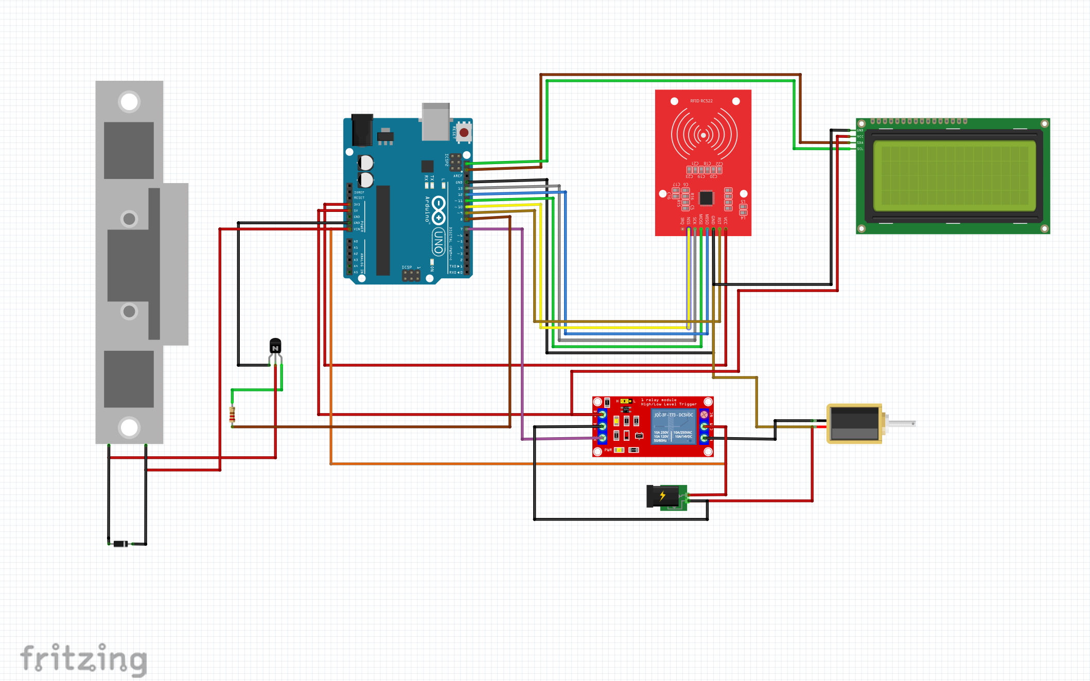
You can see that in the overall code, we have added an I2C LCD module that can also display what is going with the design to the user. There is two solenoid door locks in the circuit diagram. You are only required to use one of them. IF you choose to save cost and use the NPN transistor to dive the 12V DC solenoid door lock, you can can remove the single channel relay module and its own solenoid door lock. However, if you choose to go with the relay module approach, you have to loose the NPN transistor and its common emitter diver approach. Once everything is wired up, it’s time to write the code. The code should:
- Read the RFID tag’s ID.
- Compare the scanned ID to a list of authorized IDs.
- If the ID matches, the Arduino triggers the relay to unlock the solenoid lock.
- If not, the lock remains closed.
Here’s a basic outline of the code:
#include <SPI.h>
#include <MFRC522.h>

#define SS_PIN 10
#define RST_PIN 9
#define RELAY_PIN 7

MFRC522 rfid(SS_PIN, RST_PIN);

void setup() {
  Serial.begin(9600);
  SPI.begin();
  rfid.PCD_Init();
  pinMode(RELAY_PIN, OUTPUT);
  digitalWrite(RELAY_PIN, LOW);
}

void loop() {
  if (!rfid.PICC_IsNewCardPresent() || !rfid.PICC_ReadCardSerial()) {
    return;
  }

  String tagID = "";
  for (byte i = 0; i < rfid.uid.size; i++) {
    tagID += String(rfid.uid.uidByte[i], HEX);
  }

  if (tagID == "your_authorized_card_id") {
    Serial.println("Access Granted");
    digitalWrite(RELAY_PIN, HIGH);  // Unlock the door
    delay(5000);                    // Keep the lock open for 5 seconds
    digitalWrite(RELAY_PIN, LOW);   // Lock the door again
  } else {
    Serial.println("Access Denied");
  }

  rfid.PICC_HaltA();
}
In this code:
- The RFID reader checks if a new card is present.
- It reads the card’s ID and compares it to a pre-set authorized ID.
- If the ID matches, the relay is triggered, opening the solenoid lock for 5 seconds.
Testing the System
After uploading the code, it’s time to test the system:
- Swipe your authorized RFID card. The lock should open for a few seconds, then lock again.
- Swipe an unauthorized card, and the lock should remain closed.
If everything works correctly, congratulations—you’ve successfully built an RFID-based access control system!
Advantages of RFID Access Control Systems
Why should you consider an RFID-based access control system over other types of locks?
1. Enhanced Security
Unlike traditional keys, RFID tags are difficult to replicate, making them more secure. Additionally, you can easily deactivate lost or stolen tags without changing the lock.
2. Convenience
No more fumbling for keys! A simple swipe of a card grants you instant access.
3. Scalability
RFID systems can manage hundreds or even thousands of users, making them ideal for homes, offices, and large-scale facilities.
4. Low Maintenance
RFID systems have few moving parts and require little maintenance compared to traditional locks, which can wear out over time.
Potential Challenges and Solutions
While RFID systems are generally reliable, there are some common challenges to be aware of:
Power Outages
If your system is powered by electricity, it may stop working during a power outage. Solution: Consider adding a battery backup or using a manual override system.
Unauthorized Access
If someone gains access to an authorized RFID tag, they could breach your system. Solution: Regularly update the authorized tags list and use encryption to protect RFID data.
Tag Wear and Tear
Over time, RFID tags may wear out or break. Solution: Keep spare tags on hand and periodically check that all tags are functioning properly.
Conclusion
Building an RFID-based access control system using Arduino, an MFRC522 reader, and a solenoid lock offers a modern, efficient, and secure way to manage access to your property. By following the steps outlined in this guide, you’ll be able to create a system that not only protects your space but also adds convenience to your daily routine.
Whether you’re safeguarding your home, office, or any restricted area, this RFID access control system can give you peace of mind knowing that only authorized individuals can enter. With the flexibility to easily update and manage users, RFID technology provides a scalable and robust solution for access control.
FAQs on Building an RFID-based Access Control System
Can I use multiple RFID tags with this system?
Yes, you can program the system to recognize multiple authorized RFID tags by storing their IDs in the Arduino’s memory.
What happens if the RFID tag is lost or stolen?
You can easily remove a lost or stolen tag from the system by updating the Arduino’s code with a new list of authorized tags.
How far away can the RFID tag be read?
The MFRC522 reader has a range of about 2-5 cm, so the tag needs to be very close to the reader for it to work.
Can I use a mobile phone instead of an RFID card?
Some smartphones support NFC, which is a similar technology to RFID. However, this would require a different setup than the one described here.
Is it possible to add logging functionality to track who accessed the system?
Yes, you can add an SD card module to log the time and tag ID each time the system is accessed, giving you a record of who entered and when.