The aim of this project is to design and implement an automatic microcontroller based with Android platform control and monitoring device that uses temperature sensing IC LM35 to read and regulate the amount of heat or coldness found around the living environment of the poultry birds. Normally, a chicken body temperature is 41.5 degrees Celsius but will fluctuate depending on the temperature of its environment: provided there the presence of another vital factor, air movement (which is usually 10- 15 degrees less than the body temperature). The system would be built around a special microcontroller, ATmega328, which was programmed with the Arduino IDE on C/C++ higher languages to interact with a Wi-Fi module. The Wi-Fi module would be connected to the android phone so that the status of this poultry farm can be remotely viewed and controlled from there. The android device would run an app that would was solely developed using MIT AI2 AppInventor or RemoteXY to display the temperatures on its screen, also giving the user(s) the access to regulate the temperature through the push of a button onscreen that control the use of energy sinking tungsten AC bulbs. Now, that we have the overview of the project design. Before we go into full details on how to build the Android platform based temperature monitoring design for poultry farms, a brief introduction.
The Need for Temperature Monitoring In Poultry Farms
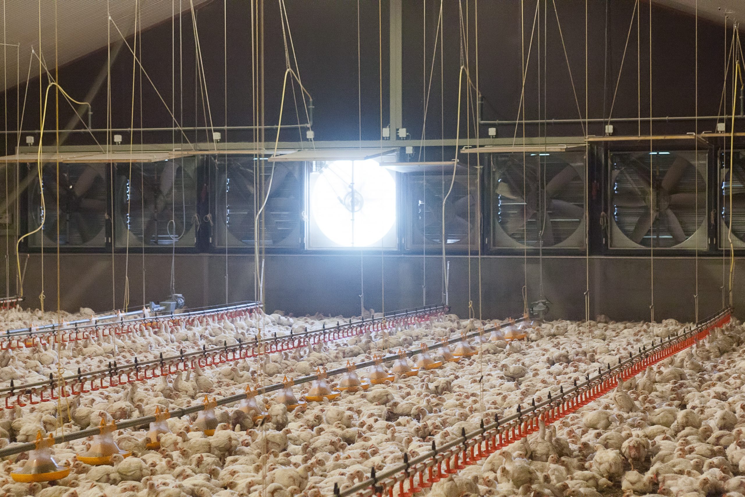
Experts tips on poultry farming says that the temperature parameter of a farm constitute 2/3 of the environmental impact on the live stocks, in this case birds. For example, Chicken eggs should be incubated between the range of 99 to 102 degrees Fahrenheit. While day old chicks sustain stable growth around 92 degree Fahrenheit. According to a research made in 2009, periods of high temperatures have a negative effect on the health and performance of domestic animals. Elevated temperature causes heat stress that increase mortality and economic loss in poultry production. For optimum capacity performance in birds, they need to be in homeostasis with their environment through the maintenance of thermobalance.
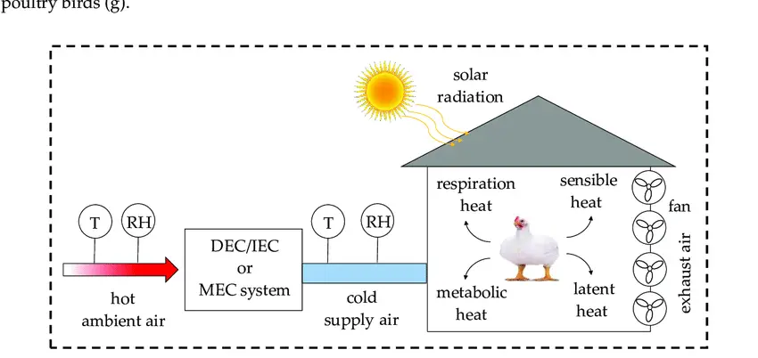
Thermobalance is the balance between heat produced by any living organism and the amount of heat given out by the same organism at any time. And this is said to be at its maximum physiological level within the thermoneutral range of any given specie. Birds, are homoeothermic mammals that maintains relatively constant body temperature, although may permit some variation within their temperature without having a significant disturbance.
Aims of the Project Design
- This system gives the controlling and monitoring of poultry farm temperature level remotely and conveniently through the use special app developed for android phones. It lifts the worry of having to go to the bird farm each to time in other to access these functions.
- The framework gives a better security access and protection to the poultry birds by allowing remote access to user or users with the android app and hence only them can control the lights and the amount of warmth in the farm.
- The project design offers vital information as to regards to the birds’ physiological behavior any time. For example, If they are feeding too much to warm themselves(LCT) or feeding less (HCT), this would always be displayed as a temperature factor on the screen.
- It helps to maintain a stable homoeothermic environment since it is programmed automatically to operate within a safe temperature margin. And also, it gives a feeling of smart technology experience since it is programmed to be user override enabled, allowing only specific users; enables smart status display and easy control from anywhere within the defined limit of the Wi-Fi wireless connection.
Components Needed Android Platform Based Temperature Monitoring Design
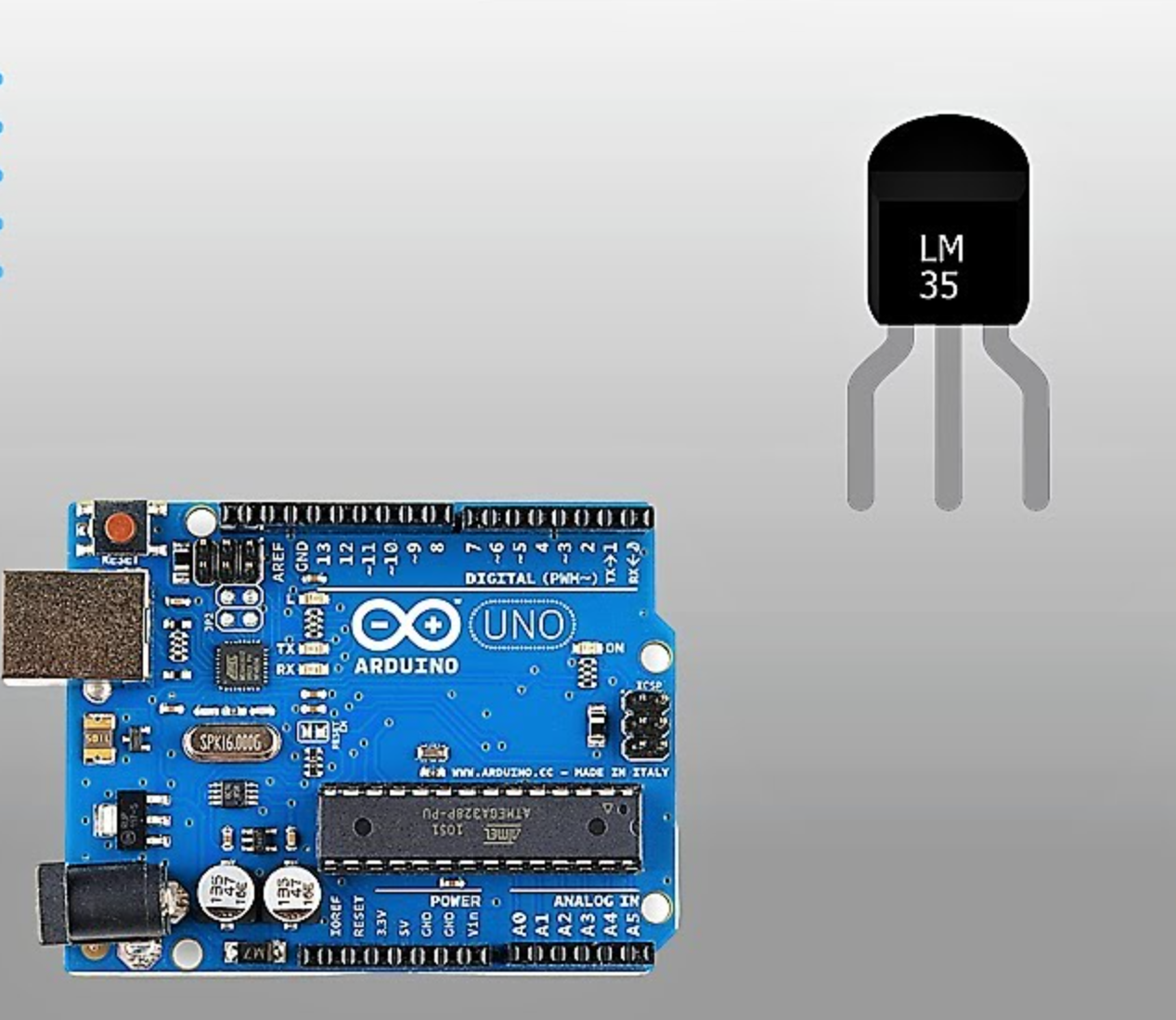
- Arduino Uno board
- LM35 Temperature Sensor IC
- 5V power supply module
- 5V Single channel relay module
- 220-240V Tungsten Alternating Current (AC) light bulb
- ESP8266-01 (ESP-01) WiFi Module
- Jumper wires
- Switch
The components listed above are the most essential. The Arduino Uno board will be the microcontroller that is used to program how the sensor, LM35 responds to the temperature around it. Since the Arduino Uno and the sensor operates on 5V, the 5V power supply supplies a Direct Current (DC) power to the components and modules used here.
The ESP-01 Module is to connect to a WiFi network that has internet access, thereby allowing the user to connect to to the poultry farm remotely, monitor it as well as control it at will. The 5V single channel relay module controls the turning on and turning off of the AC tungsten light bulb. Since the plan was to control the ambient temperature surrounding the birds using the heat that is given off by this tungsten light bulb.
How The LM35 Temperature Sensor Works
The LM35 sensor offers high accuracy in measuring ambient temperature. Its analog output is directly proportional to the Celsius temperature, making it ideal for precise temperature monitoring applications.
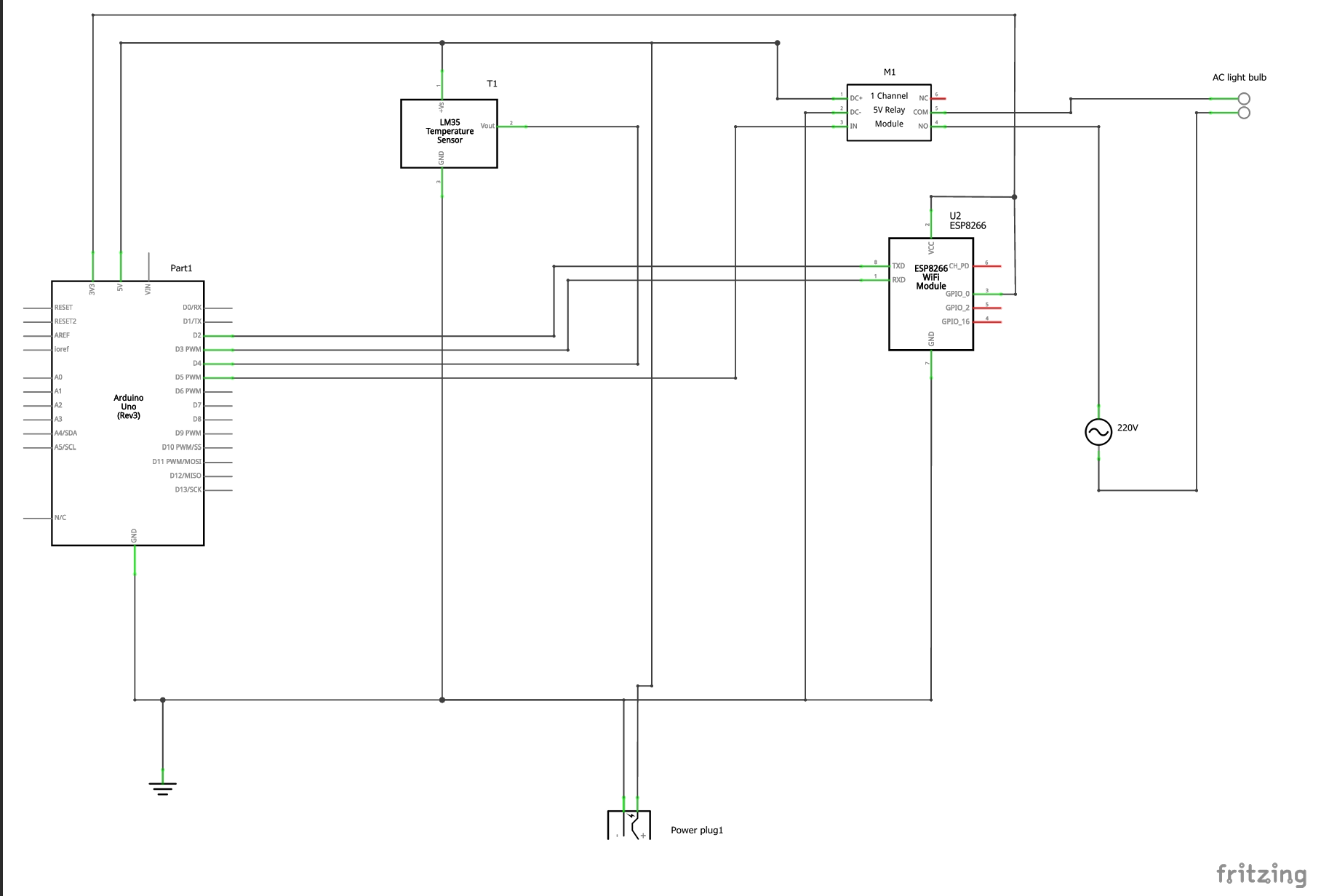
The Schematic Diagram

Circuit Connections And Explanation
1. Connecting the LM35 Temperature Sensor
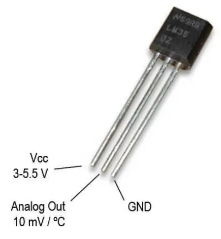
- LM35 Pinout:
- VCC: Power supply (typically 5V)
- OUT: Analog output voltage proportional to temperature
- GND: Ground
- Connections to Arduino Uno:
- VCC of LM35 to 5V on Arduino Uno
- GND of LM35 to GND on Arduino Uno
- OUT of LM35 to D4 (digital input) on Arduino Uno
2. Connecting the ESP-01 WiFi Module
- ESP-01 Pinout:
- VCC: Power supply (3.3V)
- GND: Ground
- TX: Transmit data (UART)
- RX: Receive data (UART)
- CH_PD: Chip enable (connect to 3.3V)
- GPIO0: General-purpose input/output (connect to 3.3V for normal operation)
- GPIO2: General-purpose input/output (not used in this project)
- RST: Reset (not used in this project)
- Connections to Arduino Uno:
- VCC of ESP-01 to 3.3V on Arduino Uno (important: ESP-01 operates at 3.3V, not 5V)
- GND of ESP-01 to GND on Arduino Uno
- TX of ESP-01 to RX on Arduino Uno (through a voltage divider to step down 5V to 3.3V)
- RX of ESP-01 to TX on Arduino Uno (direct connection)
- CH_PD of ESP-01 to 3.3V on Arduino Uno
- GPIO0 of ESP-01 to 3.3V on Arduino Uno
3. Connecting the Relay Module
- Relay Pinout:
- VCC: Power supply (typically 5V)
- GND: Ground
- IN: Control signal from Arduino
- COM: Common terminal for switching
- NO: Normally open terminal
- NC: Normally closed terminal
- Connections to Arduino Uno:
- VCC of Relay to 5V on Arduino Uno
- GND of Relay to GND on Arduino Uno
- IN of Relay to any digital pin on Arduino Uno (e.g., D8)
- Connections for Control (AC light Bulb):
- Connect the controlled device (heater ) to COM and NO (for normally open configuration) or COM and NC (for normally closed configuration) on the relay module.
Programming the Project Design
#include <Adafruit_Sensor.h>

#include <DHT.h>
#include <DHT_U.h>

/*
   -- Smart Farm --

   This source code of graphical user interface
   has been generated automatically by RemoteXY editor.
   To compile this code using RemoteXY library 2.3.3 or later version
   download by link http://remotexy.com/en/library/
   To connect using RemoteXY mobile app by link http://remotexy.com/en/download/
     - for ANDROID 4.1.1 or later version;
     - for iOS 1.2.1 or later version;

   This source code is free software; you can redistribute it and/or
   modify it under the terms of the GNU Lesser General Public
   License as published by the Free Software Foundation; either
   version 2.1 of the License, or (at your option) any later version.
*/

//////////////////////////////////////////////
//        RemoteXY include library          //
//////////////////////////////////////////////

// RemoteXY select connection mode and include library
#define REMOTEXY_MODE__ESP8266_HARDSERIAL_POINT

#include <RemoteXY.h>

// RemoteXY connection settings
#define REMOTEXY_SERIAL Serial
#define REMOTEXY_SERIAL_SPEED 115200
#define REMOTEXY_WIFI_SSID "DAMI FARM"
#define REMOTEXY_WIFI_PASSWORD "12345678"
#define REMOTEXY_SERVER_PORT 6377


// RemoteXY configurate
#pragma pack(push, 1)
uint8_t RemoteXY_CONF[] =
  { 255,1,0,47,1,85,0,8,45,2,
  2,1,37,28,16,8,20,31,26,12,
  2,32,31,31,79,78,0,79,70,70,
  0,67,0,1,40,98,6,1,59,61,
  7,31,26,101,67,0,1,48,98,6,
  1,73,61,7,2,26,101,67,0,1,
  56,98,6,1,88,61,7,13,26,101,
  129,0,6,2,89,16,5,5,55,10,
  2,83,109,97,114,116,32,70,97,114,
  109,0 };

// this structure defines all the variables of your control interface
struct {

    // input variable
  uint8_t SW1; // =1 if switch ON and =0 if OFF

    // output variable
  char SCREEN1[101];  // string UTF8 end zero
  char SCREEN2[101];  // string UTF8 end zero
  char SCREEN3[101];  // string UTF8 end zero

    // other variable
  uint8_t connect_flag;  // =1 if wire connected, else =0

} RemoteXY;
#pragma pack(pop)

/////////////////////////////////////////////
//           END RemoteXY include          //
/////////////////////////////////////////////

#define PIN_SW1 8

// what digital pin we're connected to
#define DHTPIN 6

// Uncomment whatever type you're using!
#define DHTTYPE DHT11   // DHT 11


DHT dht(DHTPIN, DHTTYPE);


void setup()
{
  RemoteXY_Init ();

  pinMode (PIN_SW1, OUTPUT);

dht.begin();

}
void soilMonitor() {
  // read the input on analog pin 0:
  int sensor = analogRead(A0);
  // Convert the analog reading (which goes from 0 - 1023) to a range (0 - 100):
  double TP = sensor * (100 / 1023.0);
 //dtostrf(TP, 0, 2, RemoteXY.SCREEN2);//SEND VALUE OF ADC TO SMART PHONE

int soil = TP;
if((soil < 40) || (soil == 40)  && (RemoteXY.SW1 == 0) ) {
  digitalWrite(PIN_SW1, HIGH);
 strcpy (RemoteXY.SCREEN3, "Pump in AUTO Mode");
}
}

void loop()
{
  RemoteXY_Handler ();
soilMonitor();
   // read the input on analog pin 0:
  int sensor = analogRead(A0);
  // Convert the analog reading (which goes from 0 - 1023) to a range (0 - 100):
  double TP = sensor * (100 / 1023.0);
 //dtostrf(TP, 0, 2, RemoteXY.SCREEN2);//SEND VALUE OF ADC TO SMART PHONE

int soil = TP;

//sprintf (RemoteXY.SCREEN2, "The Temperature is: %d'C___Farm Humidity is: %d", TEMP, HUM);
sprintf (RemoteXY.SCREEN1, "The Soil moistue reading is: %d", soil);

if ((soil < 60) && (RemoteXY.SW1 ==1))
{
digitalWrite(PIN_SW1, HIGH);
 strcpy (RemoteXY.SCREEN3, "Manual Override: Pump running");
}
if ((soil > 40) && (soil < 60) && (RemoteXY.SW1 == 0))
{
digitalWrite(PIN_SW1, LOW);
 strcpy (RemoteXY.SCREEN3, "Pump is not running");
}
if((soil > 60) && (RemoteXY.SW1 ==1)) {
  digitalWrite(PIN_SW1, LOW);
  strcpy (RemoteXY.SCREEN3, "Warning!!! Farm Flooded, System AUTO Shut Off Pump");
}
if((soil > 60) && (RemoteXY.SW1 ==0)) {
  digitalWrite(PIN_SW1, LOW);
  strcpy (RemoteXY.SCREEN3, "Thanks, Farm Flooding Averted.");
}

  float h = dht.readHumidity();
  // Read temperature as Celsius (the default)
  float t = dht.readTemperature();
 int Temp = t;
 int Hum = h;
   // Check if any reads failed and exit early (to try again).
  if (isnan(h) || isnan(t)) {
    strcpy (RemoteXY.SCREEN3, "Warning!!! Failed to read from DHT sensor!");
    return;
  }
sprintf (RemoteXY.SCREEN2, "Farm Humidity is: %d, Temperature is: %d'C", Hum, Temp);


}
System Architecture
The temperature monitoring system operates in two main modes: Auto Mode and User Mode.
- Auto Mode: In this mode, the system autonomously regulates the temperature based on predefined thresholds. It continuously monitors the temperature using the LM35 sensor and adjusts environmental conditions (such as ventilation or heating) to maintain optimal levels for poultry comfort.
- User Mode: The system allows manual intervention via an Android platform interface. Using a dedicated mobile application, poultry farm managers can remotely monitor real-time temperature data. They can also adjust settings on-demand to ensure the birds’ comfort and well-being.
Integration and Testing
Benefits of the System
- Enhanced Monitoring: Real-time temperature monitoring enables proactive management of poultry farm conditions.
- Remote Accessibility: Accessibility via Android platform allows farm managers to monitor and control temperature parameters remotely, improving operational efficiency.
- Data Logging and Analysis: The system can log temperature data over time, facilitating historical analysis and trend identification for informed decision-making.
Conclusion
The Android platform-based temperature monitoring system for poultry farms represents a significant advancement in agricultural technology. By leveraging Arduino Uno, LM35 temperature sensor, and ESP-01 WiFi module, poultry farmers can achieve precise temperature control and monitoring capabilities. This not only enhances the welfare of poultry birds but also optimizes farm productivity and operational efficiency.
Implementing such a system underscores the importance of integrating modern technology into traditional farming practices, paving the way for sustainable and efficient agricultural operations. For poultry farmers looking to improve temperature management and operational oversight, adopting this Android platform-based solution offers a scalable and robust approach to meet their evolving needs.