Imagine controlling your ceiling fan or standing fan with just the press of a button on an old TV remote. No more getting up from the couch or bed to adjust the fan speed or turn it off. With the power of Arduino and a few affordable components, you can turn this dream into reality. In this blog post, we’ll guide you through creating a remote-controlled fan using an Arduino, IR receiver, an old TV remote, a power supply module, and a 4-channel relay module. This project is perfect for DIY enthusiasts looking to automate home appliances, especially those with a passion for Arduino projects
Why Remote-Controlled Fan Automation?
In today’s fast-paced world, convenience is key. Home automation projects like this one can significantly enhance your daily living experience. Whether you’re looking to automate your fan for better energy efficiency, ease of use, or just as a fun project to enhance your DIY skills, this remote-controlled fan offers multiple benefits:
- Energy Efficiency: Automate your fan to switch off after a certain period, saving energy.
- Convenience: Control your fan without moving, especially helpful for those with mobility issues.
- Skill Development: Learn and apply programming, electronics, and circuit design skills.
Components and Material Required for the DIY Remote-Controlled Fan Using Arduino
Before diving into the project, let’s review the components we will need:
- Arduino Standalone Board: The microcontroller board that will control the entire system.
- IR Receiver Module TSOP1838: Detects the signals sent by the old TV remote.
- Old TV Remote: The controller for the fan, repurposed for this project.
- 4-Channel Relay Module: Controls the fan’s speed settings and power using signals from the Arduino.
- Power Supply Module: Powers the entire system.
- Fan: The ceiling or table fan that we will be automating.
- Jumper Wires and Breadboard: For connecting the components.
- Resistors and Diodes: For circuit protection and stability.
Circuit Design and Schematic
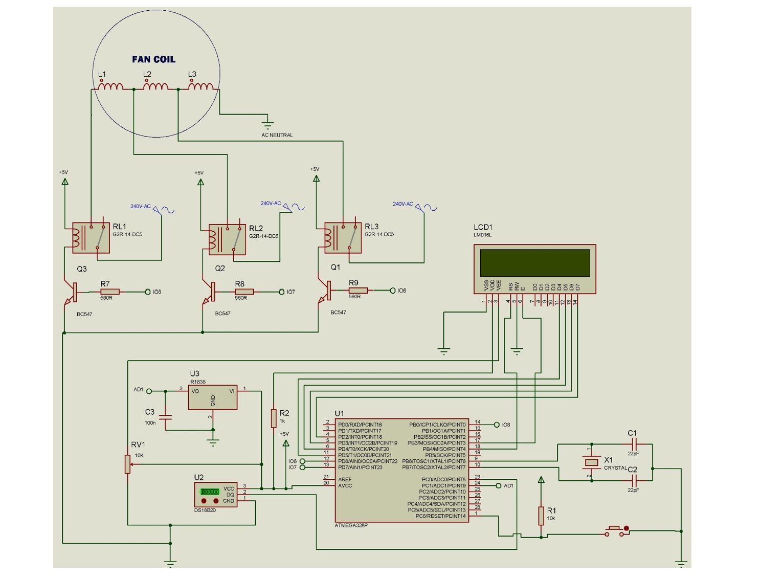
The first step is to design the circuit that will control the fan. Above is the schematic diagram that outlines how the components are connected. In the diagram above, the IR receiver is connected to one of the digital pins on the Arduino standalone board, while the relay module is connected to four other digital pins. The power supply module is connected to power the Arduino and the relay module.
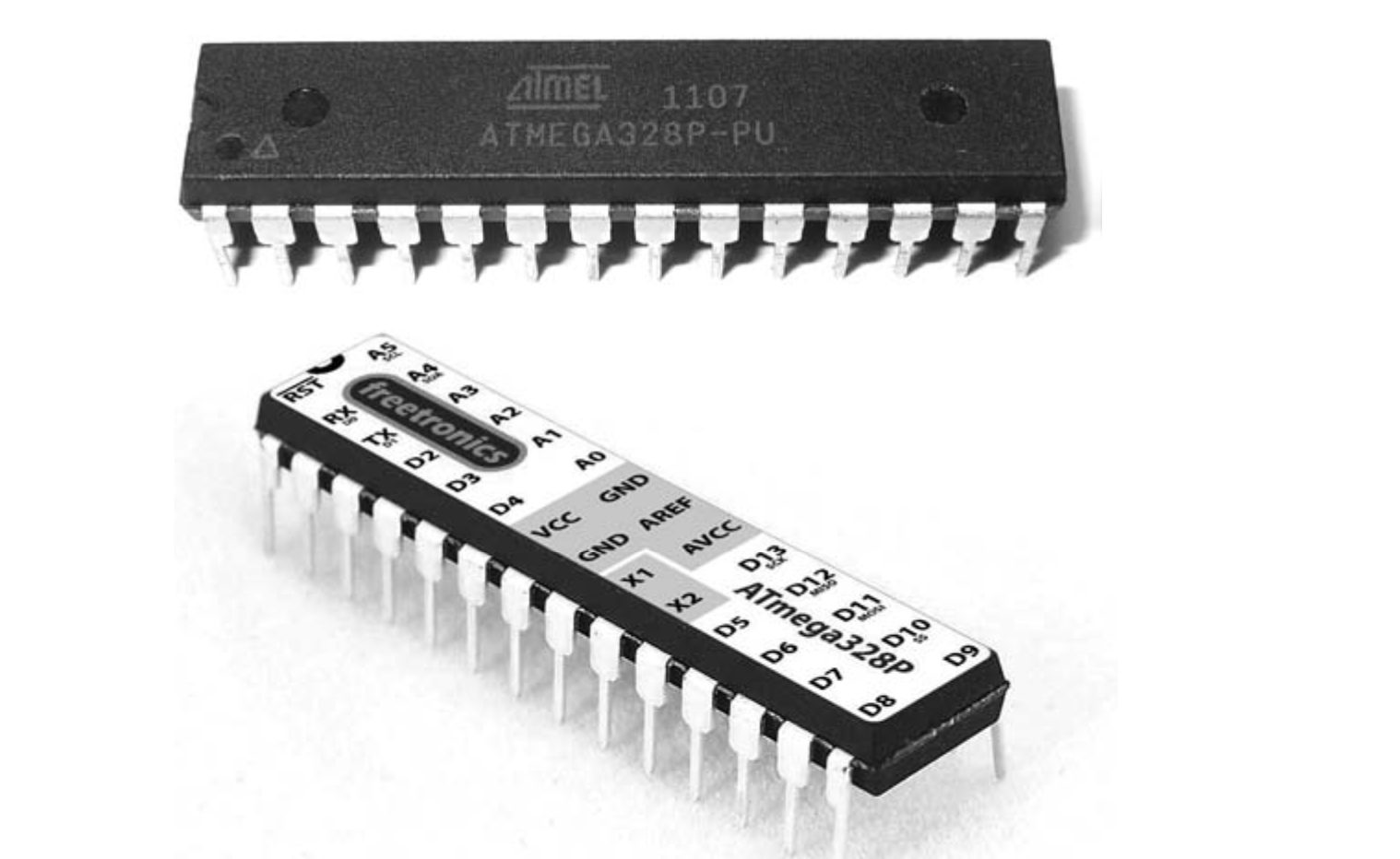
The programmable integrated circuit Atmega328p-pu served as the foundation for the microcontroller unit, which is the control component of the design. It consists of filter capacitors, crystal oscillators, and the Atmeg chip.
Setting Up the IR Receiver
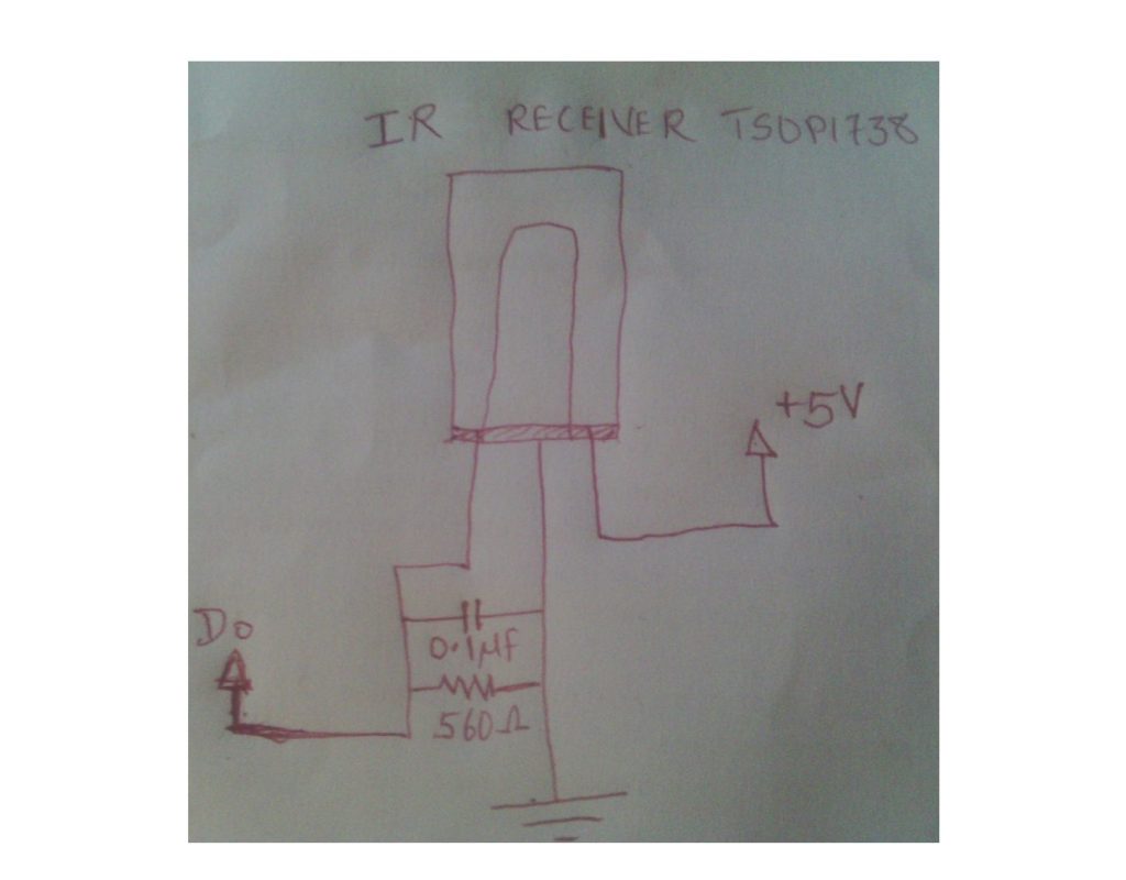
The IR receiver is a crucial component of this project, as it will decode the signals from our old TV remote. To set it up, we connected the VCC and GND pins of the IR receiver to the 5V and GND pins on the Arduino standalone board, respectively. The data pin of the IR receiver, we connected to one of the digital pins on the Arduino, pin Analog pin 1, A1.
Read Also How to Make Automatic Remote Controlled AC Fan with User Enabled Function
As was previously noted, this unit consists of the infrared receiver TSOP1738, which has three terminals: Pin 1 is the output pin, Pin 2 is connected to the ground terminal (or LOW) of the PSU, and Pin 3 is connected to the HIGH of the PSU (+5 Vcc) supply. It is referred to as the Do data pin (or terminal). The sensor (TSOP1838) is connected from the data pin to the ground via a very low capacitive capacitance in order to prevent the sensor from delivering fluctuation signals to the microcontroller standalone board as a result of IR impulses from random sources.
Setting Up The Relay Module Unit
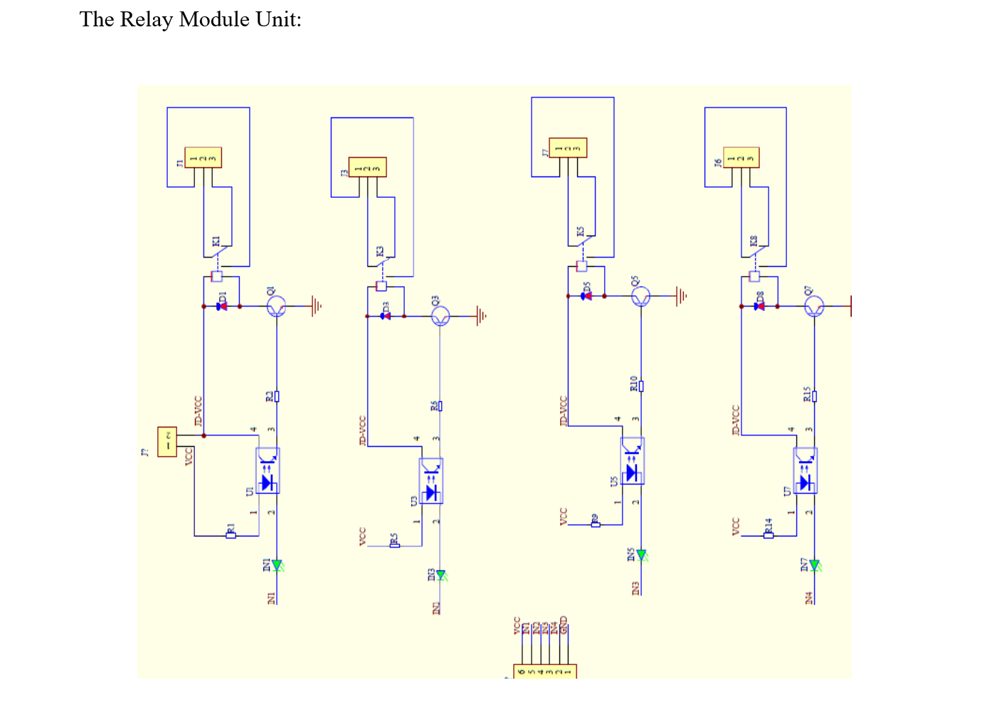
The relay module unit consists of a configuration of discrete linear components and electromagnetic switches that sense very little current input and let high voltage to pass across its switch. The optocoupler in the above-depicted module is constructed from LEDs and phototransistors, together with signal diodes for relay protection, a general-purpose NPN transistor, and a low-value resistor.
The four relays of the relay module operate as follows: starting with the first relay, which has switch K1, the anode of the optocoupler’s LED is linked to the +5v Vcc via resistor R1. In order to raise the relay coil’s coil, the collector of transistor Q1 is further given +5 volts with a shared emitter connection. As a result of current flowing through the LED’s anode, which was encased and would glow (though this could not be seen), the transistor’s base would become biased and conduct, allowing current to pass through the Vcc at the collector and, because Q1’s base is already open, through R2 to -5v (ground). The pole of the relay would shift from terminal 3 (usually closed, NC) to terminal 1 (usually open, NO) as a result, energizing the K1’s coils. The identical action is carried out by the other relays, K2, K3, and K4.
During the usage of the Relay module unit, it was discovered that the best way to the switching inputs IN1, IN2 and IN3 was to connect and PNP transistor to invert the operation. Because the design was anticipated to work on the note of; if a Digital pin of the MCU goes HIGH, this would in turn switch the pole of one of the three relays from NC to NO. but we had to go with the option of removing the optocouplers so that we could get our desired target in the use of the relay module.
Setting Up the Temperature Sensor
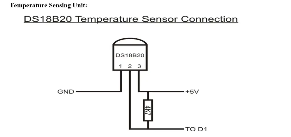
To make the project smarter, we included a temperature sensor by choosing the DS18B20 temperature sensor, The schematic diagram above is the breakdown of how it was isolated and connected to the the Arduino standalone board.
Setting Up the LCD Module for the Remote-Controlled Fan Using Arduino
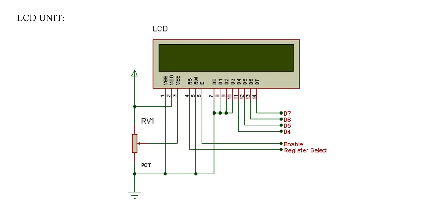
The liquid crystal display is an affordable, customizable display module that has the ability to show unique characters. An LCD with a resolution of 16 by 2 may show two lines with 16 characters each. A 5 × 7 pixel matrix displays each character. The two registers on the LCD are called Command and Data. The following describes the pins and how they work:
- Register Select (RS): this pin selects Command register when low and Data register when high.
- Read/Write (R/W): this pin writes to the register when low and reads from the register when high.
- Enable (E): this pin sends data to the Data pins when a high to low pulse is given to it.
- Pin 7 to 14 (D4 to D): these are 8-bit pins that are used to send and and receive data to/from the LCD.
- Pin 15 ( ): this is the positive (+Vcc) backlight of the LED (LED+) of the LCD. This pin is usually connected with a pullup resistor ( ≤ 1kΩ). this is important to limit current flowing in the LEDs of the LCD.
- Pin 16 (D16): this is the negative (ground ) −Vcc pin. It is connected to the ground of the DC power supply
Programming the Arduino Standalone Board
#include <LiquidCrystal.h>
#include <OneWire.h>
#include <DallasTemperature.h>
#include <IRremote.h>
// LCD pins and initialization
LiquidCrystal lcd(12, 11, 5, 4, 3, 2);
// Temperature sensor pin and initialization
#define ONE_WIRE_BUS A0
OneWire oneWire(ONE_WIRE_BUS);
DallasTemperature sensors(&oneWire);
// IR receiver pin and initialization
#define RECV_PIN A1
IRrecv irrecv(RECV_PIN);
decode_results results;
// LED pins
const int ledPins[] = {6, 7, 8}; // Array to handle LED pins more efficiently
void setup() {
lcd.begin(20, 4);
irrecv.enableIRIn();
sensors.begin();
// Set LED pins as output
for (int i = 0; i < 3; i++) {
pinMode(ledPins[i], OUTPUT);
}
// Display welcome message
lcd.setCursor(0, 0);
lcd.print("Welcome Chinny!");
lcd.setCursor(0, 1);
lcd.print("Smart FAN Project");
delay(3000);
lcd.setCursor(0, 1);
lcd.print("Please Wait.......");
delay(2000);
lcd.setCursor(0, 1);
lcd.print("Smart FAN Ready");
delay(1000);
}
void updateFanSpeed(int speed) {
// Turn off all LEDs
for (int i = 0; i < 3; i++) {
digitalWrite(ledPins[i], LOW);
}
// Turn on the LED corresponding to the fan speed
if (speed > 0 && speed <= 3) {
digitalWrite(ledPins[speed - 1], HIGH);
}
// Update LCD with the current fan speed or OFF message
lcd.setCursor(0, 1);
switch (speed) {
case 1:
lcd.print("FAN AT SPEED 1 ");
break;
case 2:
lcd.print("FAN AT SPEED 2 ");
break;
case 3:
lcd.print("FAN AT SPEED 3 ");
break;
default:
lcd.print("FAN TURNED OFF!");
break;
}
}
void displayRoomTemp(float roomTemp) {
lcd.setCursor(0, 0);
lcd.print("ROOM TEMP:");
lcd.setCursor(10, 0);
lcd.print(roomTemp);
lcd.setCursor(14, 0);
lcd.print("'C");
}
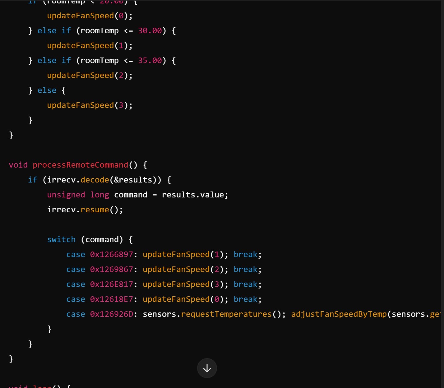
void adjustFanSpeedByTemp(float roomTemp) {
if (roomTemp < 20.00) {
updateFanSpeed(0);
} else if (roomTemp <= 30.00) {
updateFanSpeed(1);
} else if (roomTemp <= 35.00) {
updateFanSpeed(2);
} else {
updateFanSpeed(3);
}
}
void processRemoteCommand() {
if (irrecv.decode(&results)) {
unsigned long command = results.value;
irrecv.resume();
switch (command) {
case 0x1266897: updateFanSpeed(1); break;
case 0x1269867: updateFanSpeed(2); break;
case 0x126E817: updateFanSpeed(3); break;
case 0x12618E7: updateFanSpeed(0); break;
case 0x126926D: sensors.requestTemperatures(); adjustFanSpeedByTemp(sensors.getTempCByIndex(0)); break;
}
}
}
void loop() {
sensors.requestTemperatures();
float roomTemp = sensors.getTempCByIndex(0);
displayRoomTemp(roomTemp);
processRemoteCommand();
delay(50);
}
Arduino IDE Code Explanation
- Array for LEDs: The three LED pins are now stored in an array, allowing the
updateFanSpeedfunction to handle turning on and off LEDs more efficiently. - Consolidation of Functions: The functions for setting fan speed and turning off the fan have been combined into one function,
updateFanSpeed, which takes a single parameter for speed. This reduces redundancy. - Switch Case: A
switchstatement replaces the multipleif-elseblocks to handle remote commands, making the code more readable and slightly more efficient. - Temperature Display: The temperature display function
displayRoomTemphas been separated out for clarity and reuse. - Efficient Fan Speed Adjustment: The function
adjustFanSpeedByTemphandles fan speed adjustment based on temperature readings more directly, again usingupdateFanSpeed.
Assembling the Hardware
With the code ready, it’s time to assemble our project. We connected the modules with jumper wires to connect the Arduino to the relay module, the IR receiver, and the fan. Ensured that the relay module is capable of handling the power requirements of our fan. Once everything was connected, we uploaded the final code to the Arduino standalone board.
Read Also…
- Android Platform Based Temperature Monitoring Design for Poultry Farms
- How To Design An Arduino Based Automatic Gate Controller
- Smart Window Automation: Arduino-Based System for Rain, Smoke, and Gas Detection
Testing and Troubleshooting
Before finalizing the project, it’s crucial to test all functionalities. We ensured that each button on the remote correctly controls the fan’s speed and power. If something isn’t working as expected, we double-checked our connections and code. Common issues to note here are incorrect wiring, wrong HEX codes, or insufficient power supply.
Enhancing Our Project
This project can be expanded in many ways. You could add an IoT to show the current fan speed or use a Bluetooth module for smartphone control. Integrating the fan with a home automation system like Google Home or Alexa is another great way to enhance its functionality.
Conclusion
Building a remote-controlled fan with Arduino is a rewarding project that combines electronics, programming, and home automation. Whether you’re a seasoned DIY enthusiast or just starting, this project offers an excellent opportunity to enhance your skills while creating something useful. With the right components, code, and a bit of patience, you can bring a new level of convenience to your home.
Let us know if you were able to do this project and get it working in the comment section below. Thank you.
FAQs on Remote-Controlled Fan Using Arduino
1. What components are required for the remote-controlled fan project?
- Answer: The essential components include:
- Arduino board (e.g., Uno, Nano)
- IR receiver module (e.g., TSOP1738)
- Old TV remote control
- Relay module (e.g., 4-channel relay)
- Power supply module
- LCD display (optional)
- DC fan or AC fan connected through relays
- Temperature sensor (optional, e.g., DS18B20)
- Connecting wires and breadboard
- LEDs (optional for indicating fan speed)
2. How does the remote control work with the Arduino?
- Answer: The remote control sends infrared (IR) signals when a button is pressed. The IR receiver connected to the Arduino detects these signals and converts them into corresponding digital codes. The Arduino then processes these codes to control the fan’s speed or turn it on/off.
3. Can I use any remote control for this project?
- Answer: Yes, you can use almost any IR remote control, such as an old TV remote. However, you will need to map the remote’s button codes to the desired fan functions by programming the Arduino.
4. How do I decode the signals from the remote control?
- Answer: You can use the
IRremotelibrary to decode the IR signals. By running a simple sketch on your Arduino, you can capture and print the codes sent by each button on the remote. These codes are then used to control the fan.
5. What is the purpose of the relay module in this project?
- Answer: The relay module acts as an electronic switch that allows the Arduino to control high-power devices like a fan. The Arduino sends a low-power signal to the relay, which then switches the fan on or off or adjusts its speed.
6. Can I automate the fan based on temperature?
- Answer: Yes, you can incorporate a temperature sensor (e.g., DS18B20) into the project. The Arduino can read the room temperature and automatically adjust the fan’s speed based on predefined temperature thresholds.
7. What programming libraries are used in this project?
- Answer: Common libraries include:
IRremotefor handling infrared communicationOneWireandDallasTemperaturefor reading temperature from the sensorLiquidCrystalfor displaying information on an LCD screen (if used)
8. How can I modify the project to control multiple fans?
- Answer: To control multiple fans, you can expand the project by using additional relay channels and modifying the code to handle more fan outputs. The same IR remote can be used to control each fan by assigning different buttons to each fan.
9. What safety precautions should I take when working with the relay and fan?
- Answer: Ensure that the relay is rated for the voltage and current of the fan. If you’re working with an AC fan, be cautious with the wiring and ensure all connections are properly insulated. Always disconnect the power supply before making any changes to the circuit.
10. Can I use this project with a smart home system?
- Answer: Yes, with some modifications, you can integrate the project into a smart home system. For example, you can use a Wi-Fi module like the ESP8266 or ESP32 to control the fan via a mobile app or through a voice assistant like Google Home or Amazon Alexa.
11. What are some potential improvements or extensions for this project?
- Answer: Potential improvements include:
- Adding Wi-Fi or Bluetooth control.
- Integrating with a smart home platform.
- Adding more sensors, like humidity or motion sensors, to enhance automation.
- Implementing a feedback system to monitor fan speed and status remotely.