If you’ve ever wanted to build your own temperature monitoring system, you’re in for a treat! Today, we’ll show you how to create a digital temperature monitor using the LM35 sensor and Arduino. Whether you’re a beginner or an electronics enthusiast, this hands-on tutorial will guide you through each step, making it easy and fun. Ready to dive in? Let’s get started!
What is an LM35 Sensor, and Why Use It?
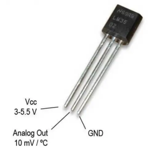
The LM35 is a tiny but powerful temperature sensor that outputs an analog voltage proportional to the temperature. It’s highly accurate, easy to use, and doesn’t require calibration, making it perfect for DIY projects like ours.
Why choose LM35 over other sensors? Simple:
- High Precision: It offers an accuracy of ±0.5°C.
- Wide Range: Measures temperatures from -55°C to +150°C.
- Effortless Interfacing: Directly compatible with Arduino’s analog pins.
Read Also: Light-Activated LED: Use an LDR to Turn An LED On In The Dark
Components You’ll Need
Before we dive into the wiring and code, let’s gather the necessary components.
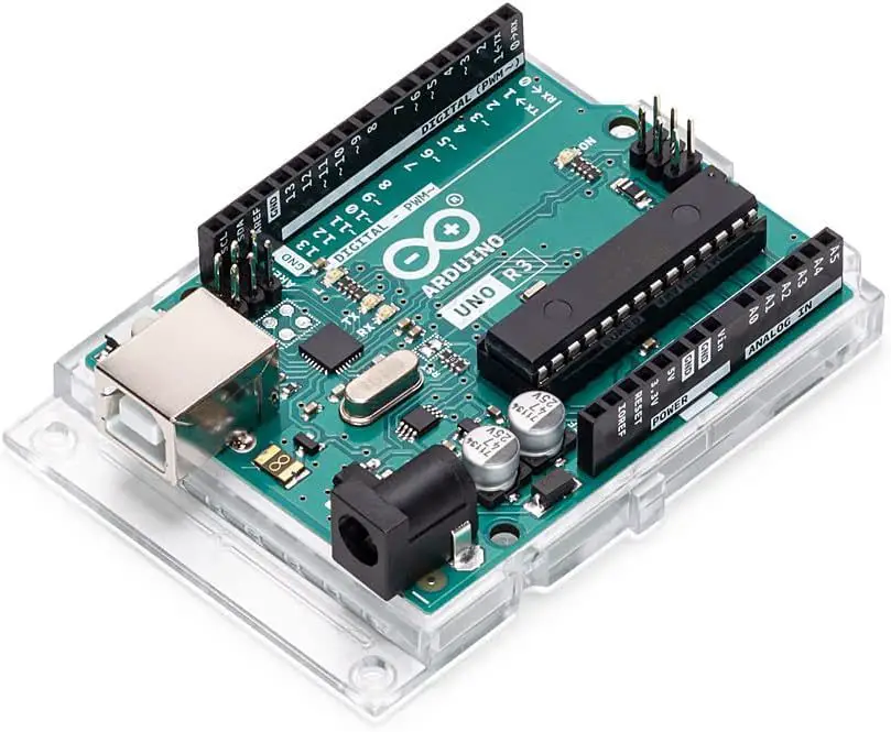
- Arduino Board (Uno)
- LM35 Temperature Sensor
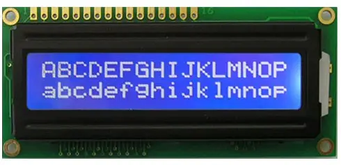
- 16×2 LCD Module (optional for display)
- Potentiometer (for LCD contrast adjustment)
- Breadboard and Jumper Wires
- Power Source (USB cable or battery)
- 10kΩ Resistor (optional for pull-down configuration)
Read Also: Smart Doorbell for Home Automation Arduino ESP32 Cam
How Does the LM35 Work?
The LM35 generates a voltage output that increases linearly with the temperature. For every degree Celsius, the sensor produces 10mV. For instance:
- At 25°C, it outputs 250mV.
- At 100°C, it outputs 1000mV.
This analog voltage is read by the Arduino’s ADC (Analog-to-Digital Converter), which converts it into a digital value. With some simple math, we can display the actual temperature in Celsius.
Step-by-Step Guide to Building the Project
Let’s break this project into bite-sized steps for better understanding and execution.
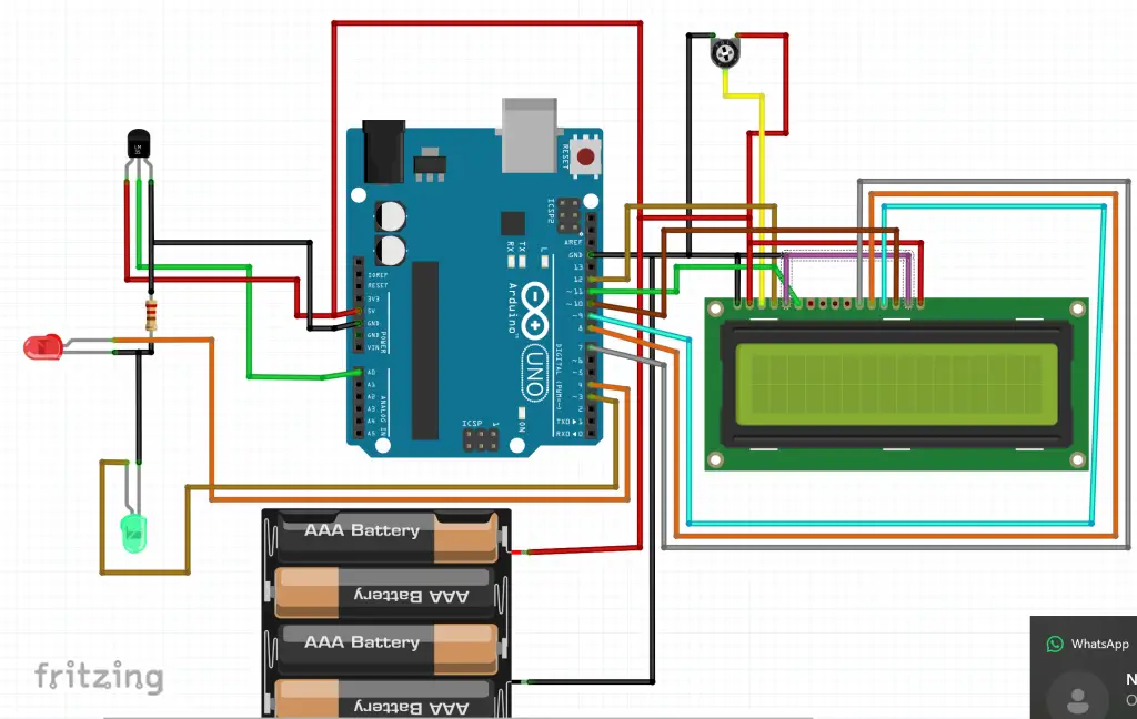
Digital Temperature Monitor Circuit Diagram: Setting Up the Circuit
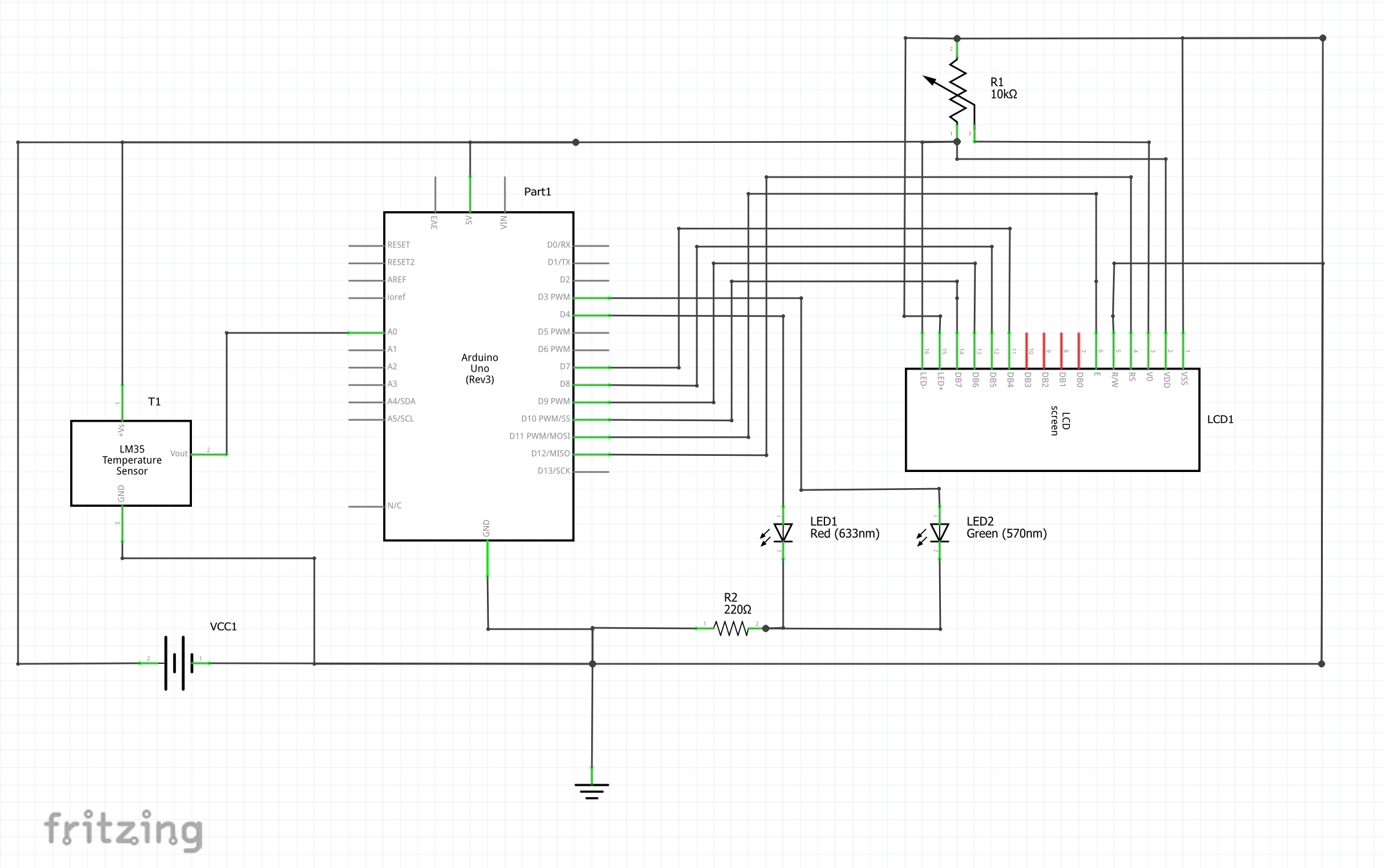
Grab your breadboard and components. Here’s how to wire everything:
Explanation of the circuit diagram
- Connect the LM35:
- Pin 1 (VCC) → 5V on Arduino
- Pin 2 (OUT) → A0 on Arduino
- Pin 3 (GND) → GND on Arduino
- Hook Up the LCD (Optional):
- Connect the LCD module using jumper wires. Use a potentiometer to adjust its contrast.
- Link the LCD pins to the Arduino according to its datasheet.
- Power the Setup:
- Use a USB cable or a battery pack to power the Arduino. You can still used rechargeable batteries as shown in the circuit diagram below.
Writing the Arduino Code
Now that the hardware is set, let’s dive into the software. Open the Arduino IDE and paste the following code:
#include <LiquidCrystal.h>

// Initialize LCD (RS, EN, D4, D5, D6, D7)
LiquidCrystal lcd(12, 11, 10, 9, 8, 7);

int sensorPin = A0; // LM35 connected to A0
float temperature;

void setup() {
  lcd.begin(16, 2); // Set up the LCD's number of columns and rows
  lcd.print("Temp Monitor"); // Display a welcome message
  delay(2000);
  lcd.clear();
}

void loop() {
  int sensorValue = analogRead(sensorPin); // Read analog value
  temperature = (sensorValue * 5.0 * 100.0) / 1024.0; // Convert to Celsius

  lcd.setCursor(0, 0);
  lcd.print("Temp: ");
  lcd.print(temperature);
  lcd.print(" C");

  delay(1000); // Update every second
}
Uploading the Code
- Connect your Arduino to your computer using a USB cable.
- Select the correct Board and Port in the Tools menu of the Arduino IDE.
- Hit the Upload button and watch the magic unfold!
Testing Our Temperature Monitor
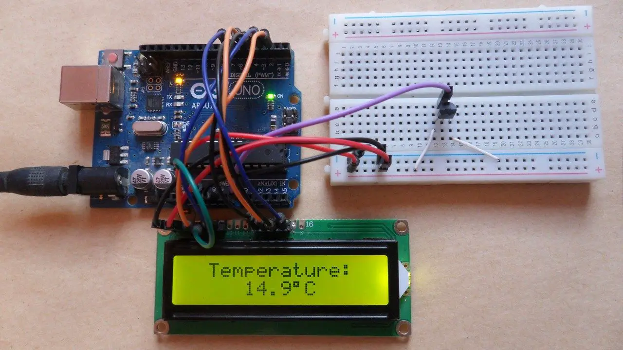
Once the code is uploaded, our LCD will display the current temperature. If the setup doesn’t work as expected:
- Double-check the wiring: Ensure all connections are secure and correct.
- Adjust the contrast: Use the potentiometer to fine-tune the LCD display.
Customizing Your Project
Want to make your project even cooler? Here are a few ideas:
Adding Fahrenheit Conversion
Modify the Arduino code to include temperature in Fahrenheit:
float fahrenheit = (temperature * 9.0 / 5.0) + 32.0;
lcd.setCursor(0, 1);
lcd.print("Temp: ");
lcd.print(fahrenheit);
lcd.print(" F");
Introducing Alerts
We added two LEDs, red and green color to light up if the temperature exceeds a certain threshold.
int greenLedPin = 4; // Connect an LED to pin 4
int redLedPin = 3;

void setup() {
  pinMode(greenLedPin, OUTPUT);
pinMode(redLedPin, OUTPUT);
}

void loop() {
  if (temperature > 60) { // Threshold temperature
    digitalWrite(redLedPin, HIGH);
digitalWrite(greenLedPin, LOW);
  } else {
    digitalWrite(redLedPin, LOW);
digitalWrite(greenLedPin, HIGH);
  }
}
Why Build a Digital Temperature Monitor?
Temperature monitoring isn’t just fun—it’s practical! From keeping an eye on weather conditions to monitoring home appliances, the applications are endless. This DIY project also strengthens your understanding of analog-to-digital conversion and sensor interfacing.
Troubleshooting Tips
Building this project is relatively simple, but you might face a few hiccups. Here’s how to tackle them:
- Incorrect Readings: Ensure the LM35 sensor is wired correctly.
- LCD Not Displaying Data: Double-check the connections and adjust the potentiometer.
- Arduino Not Uploading Code: Confirm that the correct board and port are selected.
Expanding Your Knowledge
Feel like exploring further? Here’s how you can take this project to the next level:
- IoT Integration: Use an ESP8266 module to send temperature data to an IoT platform.
- Data Logging: Add an SD card module to record temperature readings over time.
- Mobile Notifications: Send alerts to your smartphone using a GSM module.
Conclusion
Congratulations! You’ve just built your very own digital temperature monitor using an LM35 sensor and Arduino. This project is more than a DIY—it’s a stepping stone to mastering electronics and automation. Whether you display the data on an LCD, log it for analysis, or send it to the cloud, the possibilities are limitless.
So, what’s your next project? Share your thoughts in the comments below. We’d love to hear from you!
FAQs
1. Can I use a different temperature sensor for this project?
Yes, you can use other sensors like DHT11 or DS18B20, but the wiring and code will vary slightly.
2. Why is my LM35 giving incorrect readings?
Check the wiring and ensure the sensor isn’t exposed to extreme conditions. Double-check your voltage source as well.
3. How can I make this project portable?
Use a battery pack or power bank to run the Arduino. You can also design a custom PCB for compactness.
4. What is the maximum temperature the LM35 can measure?
The LM35 measures temperatures up to 150°C but operates best within its specified range of -55°C to +150°C.
5. Can I use this project for industrial applications?
This DIY monitor is more suited for educational and hobbyist purposes. For industrial use, consider more robust and precise sensors.